- Pulse Circuits Time Base Generators
- Time Base Generators (Overview)
- Types of Time Base Generators
- Bootstrap Time Base Generator
- Miller Sweep Generator
- Pulse Circuits Sweep Circuits
- Unijunction Transistor
- UJT as Relaxation Oscillator
- Pulse Circuits - Synchronization
- Pulse Circuits - Blocking Oscillators
- Pulse Circuits Sampling Gates
- Pulse Circuits - Sampling Gates
- Unidirectional Sampling Gate
- Unidirectional with More Inputs
- Bidirectional Sampling Gates
- Pulse Circuits Useful Resources
- Pulse Circuits - Quick Guide
- Pulse Circuits - Useful Resources
- Pulse Circuits - Discussion
Pulse Circuits - Sampling Gates
Up to now, we have come across different Pulse circuits. At times, we get the need to restrict the application of such pulse inputs to certain time periods. The circuit that helps us in this aspect is the Sampling gate circuit. These are also called as linear gates or transmission gates or selection circuits.
These sampling gates help in selecting the transmission signal in a certain time interval, for which the output signal is same as input signal or zero otherwise. That time period is selected using a control signal or selection signal.
Sampling Gates
For a Sampling gate, the output signal must be same as the input or proportional to the input signal in a selected time interval and should be zero otherwise. That selected time period is called as Transmission Period and the other time period is called as Non-transmission Period. This is selected using a control signal indicated by VC. The following figure explain this point.
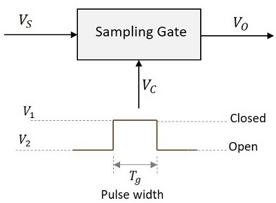
When the control signal VC is at V1, the sampling gate is closed and when VC is at V2, it is open. The pulse width Tg indicates the time period for which the gate pulse is applied.
Types of Sampling Gates
The types of Sampling gates include −
Unidirectional sampling sgates − These type of sampling gates can pass either positive or negative going pulses through them. They are constructed using diodes.
Bidirectional sampling gate − These type of sampling gates can pass both positive and negative going pulses through them. They are constructed using either diodes or BJTs.
Types of Switches Used
The sampling gates can be constructed using series or shunt switches. The time period for which the switch has to be open or close is determined by the gating pulse signal. These switches are replaced by active elements like diodes and transistors.
The following figure shows the block diagrams of sampling gates using series and shunt switches.
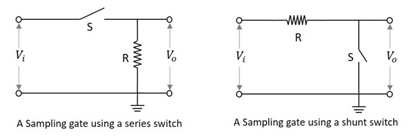
Sampling Gate using a Series Switch
In this type of switch, if the switch S is closed, the output will be exactly equal or proportional to the input. That time period will be the Transmission Period.
If the switch S is open, the output will be zero or ground signal. That time period will be the Non-transmission Period.
Sampling Gate using a Shunt Switch
In this type of switch, if the switch S is closed, the output will be zero or ground signal. That time period will be the Non-transmission Period.
If the switch S is open, the output will be exactly equal or proportional to the input. That time period will be the Transmission Period.
The sampling gates are entirely different from logic gates of digital circuits. They are also represented by pulses or voltage levels. But they are digital gates and their output is not the exact replica of the input. Whereas the sampling gate circuits are the analog gates whose output is exact replica of the input.
In the coming chapters, we will discuss the types of sampling gates.
