- Pulse Circuits Time Base Generators
- Time Base Generators (Overview)
- Types of Time Base Generators
- Bootstrap Time Base Generator
- Miller Sweep Generator
- Pulse Circuits Sweep Circuits
- Unijunction Transistor
- UJT as Relaxation Oscillator
- Pulse Circuits - Synchronization
- Pulse Circuits - Blocking Oscillators
- Pulse Circuits Sampling Gates
- Pulse Circuits - Sampling Gates
- Unidirectional Sampling Gate
- Unidirectional with More Inputs
- Bidirectional Sampling Gates
- Pulse Circuits Useful Resources
- Pulse Circuits - Quick Guide
- Pulse Circuits - Useful Resources
- Pulse Circuits - Discussion
Bidirectional Sampling Gates
Bidirectional gates, unlike unidirectional ones, transmit signals of both positive and negative polarities. These gates can be constructed using either transistors or diodes. From different types of circuits, let us go through a circuit made up of transistors and another made up of diodes.
Bidirectional Sampling Gates using Transistors
A basic bidirectional sampling gate consists of a transistor and three resistors. The input signal voltage VS and the control input voltage VC are applied through the summing resistors to the base of the transistor. The circuit diagram given below shows the bidirectional sampling gate using transistor.
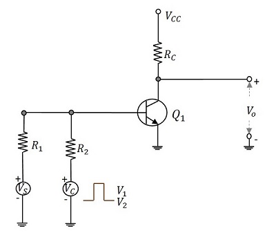
The control input VC applied here is a pulse waveform with two levels V1 and V2 and pulse width tp. This pulse width decides the desired transmission interval. The gating signal allows the input to get transmitted. When the gating signal is at its lower level V2, the transistor goes into active region. So, until the gating input is maintained at its upper level, signals of either polarity, which appear at the base of the transistor will be sampled and appear amplified at the output.
Four Diode Bidirectional Sampling Gate
Bidirectional sampling gate circuit is made using diodes also. A two diode bidirectional sampling gate is the basic one in this model. But it has few disadvantages such as
- It has low gain
- It is sensitive to the imbalances of control voltage
- Vn (min) may be excessive
- Diode capacitance leakage is present
A four diode bidirectional sampling gate was developed, improving these features. A two bidirectional sampling gate circuit was improved adding two more diodes and two balanced voltages +v or v to make the circuit of a four diode bidirectional sampling gate as shown in the figure.
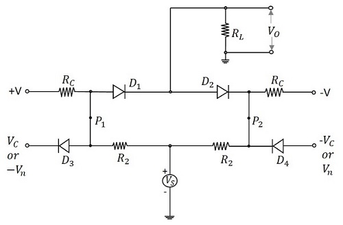
The control voltages VC and VC reverse bias the diodes D3 and D4 respectively. The voltages +v and v forward bias the diodes D1 and D2 respectively. The signal source is coupled to the load through the resistors R2 and the conducting diodes D1 and D2. As the diodes D3 and D4 are reverse biased, they are open and disconnect the control signals from gate. So, an imbalance in control signals will not affect the output.
When the control voltages applied are Vn and Vn, then the diodes D3 and D4 conduct. The points P2 and P1 are clamped to these voltages, which make the diodes D1 and D2 revere biased. Now, the output is zero.
During transmission, the diodes D3 and D4 are OFF. The gain A of the circuit is given by
$$A = \frac{R_C}{R_C + R_2} \times \frac{R_L}{R_L + (R_s/2)}$$
Hence the choice of application of control voltages enables or disables the transmission. The signals of either polarities are transmitted depending upon the gating inputs.
Applications of Sampling Gates
There are many applications of sampling gate circuits. The most common ones are as follows −
- Sampling scopes
- Multiplexers
- Sample and hold circuits
- Digital to Analog Converters
- Chopped Stabilizer Amplifiers
Among the applications of sampling gate circuits, the Sampling scope circuit is prevalent. Let us try to have an idea on the block diagram of sampling scope.
Sampling Scope
In the sampling scope, the display consists of a sequence of samples of input waveform. Each of those samples are taken at a time progressively delayed with respect to some reference point in the waveform. This is the working principle of sampling scope which is shown below in the block diagram.
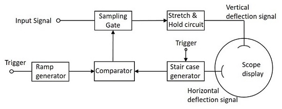
The ramp generator and the stair case generator generates the waveforms according to the trigger inputs applied. The comparator compares both of these signals and generates the output which is then given to the sampling gate circuit as a control signal.
As and when the control input is high the input at the sampling gate is delivered to the output and whenever the control input is low, the input is not transmitted.
While taking the samples, they are chosen at the time instants, which are progressively delayed by equal increments. The samples consist of a pulse whose duration is equal to the duration of the sampling gate control and whose amplitude is determined by the magnitude of the input signal at the sampling time. The pulse width then produced will be low.
Just like in the Pulse modulation, the signal has to be sampled and hold. But as the pulse width is low, it is amplified by an amplifier circuit so as to stretch and then given to a diode-capacitor combination circuit so as to hold the signal, to fill the interval of the next sample. The output this circuit is given to the vertical deflection plates and the output of sweep circuit is given to the horizontal deflection plates of the sampling scope to display the output waveform.
