
- Control Systems - Home
- Control Systems - Introduction
- Control Systems - Feedback
- Mathematical Models
- Modelling of Mechanical Systems
- Electrical Analogies of Mechanical Systems
- Control Systems - Block Diagrams
- Block Diagram Algebra
- Block Diagram Reduction
- Signal Flow Graphs
- Mason's Gain Formula
- Time Response Analysis
- Response of the First Order System
- Response of Second Order System
- Time Domain Specifications
- Steady State Errors
- Control Systems - Stability
- Control Systems - Stability Analysis
- Control Systems - Root Locus
- Construction of Root Locus
- Frequency Response Analysis
- Control Systems - Bode Plots
- Construction of Bode Plots
- Control Systems - Polar Plots
- Control Systems - Nyquist Plots
- Control Systems - Compensators
- Control Systems - Controllers
- Control Systems - State Space Model
- State Space Analysis
Control Systems - Time Response Analysis
We can analyze the response of the control systems in both the time domain and the frequency domain. We will discuss frequency response analysis of control systems in later chapters. Let us now discuss about the time response analysis of control systems.
What is Time Response?
If the output of control system for an input varies with respect to time, then it is called the time response of the control system. The time response consists of two parts.
- Transient response
- Steady state response
The response of control system in time domain is shown in the following figure.
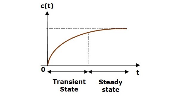
Here, both the transient and the steady states are indicated in the figure. The responses corresponding to these states are known as transient and steady state responses.
Mathematically, we can write the time response c(t) as
$$c(t)=c_{tr}(t)+c_{ss}(t)$$
Where,
- ctr(t) is the transient response
- css(t) is the steady state response
Transient Response
After applying input to the control system, output takes certain time to reach steady state. So, the output will be in transient state till it goes to a steady state. Therefore, the response of the control system during the transient state is known as transient response.
The transient response will be zero for large values of t. Ideally, this value of t is infinity and practically, it is five times constant.
Mathematically, we can write it as
$$\lim_{t\rightarrow \infty }c_{tr}(t)=0$$
Steady state Response
The part of the time response that remains even after the transient response has zero value for large values of t is known as steady state response. This means, the transient response will be zero even during the steady state.
Example
Let us find the transient and steady state terms of the time response of the control system $c(t)=10+5e^{-t}$
Here, the second term $5e^{-t}$ will be zero as t denotes infinity. So, this is the transient term. And the first term 10 remains even as t approaches infinity. So, this is the steady state term.
Standard Test Signals
The standard test signals are impulse, step, ramp and parabolic. These signals are used to know the performance of the control systems using time response of the output.
Unit Impulse Signal
A unit impulse signal, δ(t) is defined as
$\delta (t)=0$ for $t\neq 0$
and $\int_{0^-}^{0^+} \delta (t)dt=1$
The following figure shows unit impulse signal.
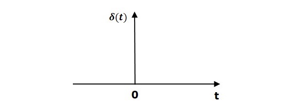
So, the unit impulse signal exists only at t is equal to zero. The area of this signal under small interval of time around t is equal to zero is one. The value of unit impulse signal is zero for all other values of t.
Unit Step Signal
A unit step signal, u(t) is defined as
$$u(t)=1;t\geq 0$$
$=0; t<0$
Following figure shows unit step signal.
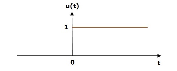
So, the unit step signal exists for all positive values of t including zero. And its value is one during this interval. The value of the unit step signal is zero for all negative values of t.
Unit Ramp Signal
A unit ramp signal, r(t) is defined as
$$r(t)=t; t\geq 0$$
$=0; t<0$
We can write unit ramp signal, $r(t)$ in terms of unit step signal, $u(t)$ as
$$r(t)=tu(t)$$
Following figure shows unit ramp signal.
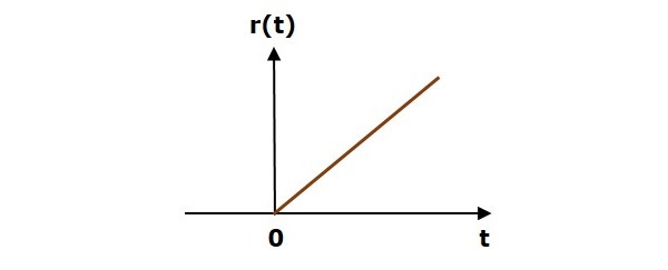
So, the unit ramp signal exists for all positive values of t including zero. And its value increases linearly with respect to t during this interval. The value of unit ramp signal is zero for all negative values of t.
Unit Parabolic Signal
A unit parabolic signal, p(t) is defined as,
$$p(t)=\frac{t^2}{2}; t\geq 0$$
$=0; t<0$
We can write unit parabolic signal, $p(t)$ in terms of the unit step signal, $u(t)$ as,
$$p(t)=\frac{t^2}{2}u(t)$$
The following figure shows the unit parabolic signal.
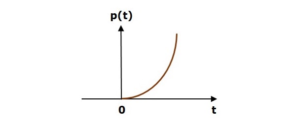
So, the unit parabolic signal exists for all the positive values of t including zero. And its value increases non-linearly with respect to t during this interval. The value of the unit parabolic signal is zero for all the negative values of t.