- Control Systems - Home
- Control Systems - Introduction
- Control Systems - Feedback
- Mathematical Models
- Modelling of Mechanical Systems
- Electrical Analogies of Mechanical Systems
- Control Systems - Block Diagrams
- Block Diagram Algebra
- Block Diagram Reduction
- Signal Flow Graphs
- Mason's Gain Formula
- Time Response Analysis
- Response of the First Order System
- Response of Second Order System
- Time Domain Specifications
- Steady State Errors
- Control Systems - Stability
- Control Systems - Stability Analysis
- Control Systems - Root Locus
- Construction of Root Locus
- Frequency Response Analysis
- Control Systems - Bode Plots
- Construction of Bode Plots
- Control Systems - Polar Plots
- Control Systems - Nyquist Plots
- Control Systems - Compensators
- Control Systems - Controllers
- Control Systems - State Space Model
- State Space Analysis
Control Systems - Mathematical Models
The control systems can be represented with a set of mathematical equations known as mathematical model. These models are useful for analysis and design of control systems. Analysis of control system means finding the output when we know the input and mathematical model. Design of control system means finding the mathematical model when we know the input and the output.
The following mathematical models are mostly used.
- Differential equation model
- Transfer function model
- State space model
Let us discuss the first two models in this chapter.
Differential Equation Model
Differential equation model is a time domain mathematical model of control systems. Follow these steps for differential equation model.
Apply basic laws to the given control system.
Get the differential equation in terms of input and output by eliminating the intermediate variable(s).
Example
Consider the following electrical system as shown in the following figure. This circuit consists of resistor, inductor and capacitor. All these electrical elements are connected in series. The input voltage applied to this circuit is $v_i$ and the voltage across the capacitor is the output voltage $v_o$.
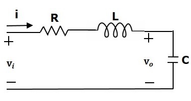
Mesh equation for this circuit is
$$v_i=Ri+L\frac{\text{d}i}{\text{d}t}+v_o$$
Substitute, the current passing through capacitor $i=c\frac{\text{d}v_o}{\text{d}t}$ in the above equation.
$$\Rightarrow\:v_i=RC\frac{\text{d}v_o}{\text{d}t}+LC\frac{\text{d}^2v_o}{\text{d}t^2}+v_o$$
$$\Rightarrow\frac{\text{d}^2v_o}{\text{d}t^2}+\left ( \frac{R}{L} \right )\frac{\text{d}v_o}{\text{d}t}+\left ( \frac{1}{LC} \right )v_o=\left ( \frac{1}{LC} \right )v_i$$
The above equation is a second order differential equation.
Transfer Function Model
Transfer function model is an s-domain mathematical model of control systems. The Transfer function of a Linear Time Invariant (LTI) system is defined as the ratio of Laplace transform of output and Laplace transform of input by assuming all the initial conditions are zero.
If $x(t)$ and $y(t)$ are the input and output of an LTI system, then the corresponding Laplace transforms are $X(s)$ and $Y(s)$.
Therefore, the transfer function of LTI system is equal to the ratio of $Y(s)$ and $X(s)$.
$$i.e.,\: Transfer\: Function =\frac{Y(s)}{X(s)}$$
The transfer function model of an LTI system is shown in the following figure.
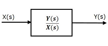
Here, we represented an LTI system with a block having transfer function inside it. And this block has an input $X(s)$ & output $Y(s)$.
Example
Previously, we got the differential equation of an electrical system as
$$\frac{\text{d}^2v_o}{\text{d}t^2}+\left ( \frac{R}{L} \right )\frac{\text{d}v_o}{\text{d}t}+\left ( \frac{1}{LC} \right )v_o=\left ( \frac{1}{LC} \right )v_i$$
Apply Laplace transform on both sides.
$$s^2V_o(s)+\left ( \frac{sR}{L} \right )V_o(s)+\left ( \frac{1}{LC} \right )V_o(s)=\left ( \frac{1}{LC} \right )V_i(s)$$
$$\Rightarrow \left \{ s^2+\left ( \frac{R}{L} \right )s+\frac{1}{LC} \right \}V_o(s)=\left ( \frac{1}{LC} \right )V_i(s)$$
$$\Rightarrow \frac{V_o(s)}{V_i(s)}=\frac{\frac{1}{LC}}{s^2+\left ( \frac{R}{L} \right )s+\frac{1}{LC}}$$
Where,
$v_i(s)$ is the Laplace transform of the input voltage $v_i$
$v_o(s)$ is the Laplace transform of the output voltage $v_o$
The above equation is a transfer function of the second order electrical system. The transfer function model of this system is shown below.
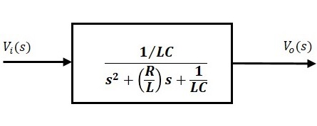
Here, we show a second order electrical system with a block having the transfer function inside it. And this block has an input $V_i(s)$ & an output $V_o(s)$.
