
- Control Systems - Home
- Control Systems - Introduction
- Control Systems - Feedback
- Mathematical Models
- Modelling of Mechanical Systems
- Electrical Analogies of Mechanical Systems
- Control Systems - Block Diagrams
- Block Diagram Algebra
- Block Diagram Reduction
- Signal Flow Graphs
- Mason's Gain Formula
- Time Response Analysis
- Response of the First Order System
- Response of Second Order System
- Time Domain Specifications
- Steady State Errors
- Control Systems - Stability
- Control Systems - Stability Analysis
- Control Systems - Root Locus
- Construction of Root Locus
- Frequency Response Analysis
- Control Systems - Bode Plots
- Construction of Bode Plots
- Control Systems - Polar Plots
- Control Systems - Nyquist Plots
- Control Systems - Compensators
- Control Systems - Controllers
- Control Systems - State Space Model
- State Space Analysis
Control Systems - Block Diagram Reduction
The concepts discussed in the previous chapter are helpful for reducing (simplifying) the block diagrams.
Block Diagram Reduction Rules
Follow these rules for simplifying (reducing) the block diagram, which is having many blocks, summing points and take-off points.
Rule 1 − Check for the blocks connected in series and simplify.
Rule 2 − Check for the blocks connected in parallel and simplify.
Rule 3 − Check for the blocks connected in feedback loop and simplify.
Rule 4 − If there is difficulty with take-off point while simplifying, shift it towards right.
Rule 5 − If there is difficulty with summing point while simplifying, shift it towards left.
Rule 6 − Repeat the above steps till you get the simplified form, i.e., single block.
Note − The transfer function present in this single block is the transfer function of the overall block diagram.
Example
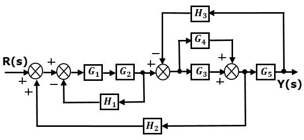
Consider the block diagram shown in the following figure. Let us simplify (reduce) this block diagram using the block diagram reduction rules.
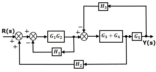
Step 1 − Use Rule 1 for blocks $G_1$ and $G_2$. Use Rule 2 for blocks $G_3$ and $G_4$. The modified block diagram is shown in the following figure.
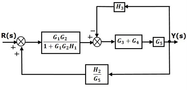
Step 2 − Use Rule 3 for blocks $G_1G_2$ and $H_1$. Use Rule 4 for shifting take-off point after the block $G_5$. The modified block diagram is shown in the following figure.
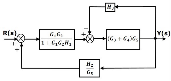
Step 3 − Use Rule 1 for blocks $(G_3 + G_4)$ and $G_5$. The modified block diagram is shown in the following figure.
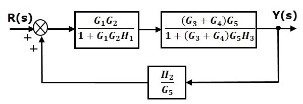
Step 4 − Use Rule 3 for blocks $(G_3 + G_4)G_5$ and $H_3$. The modified block diagram is shown in the following figure.
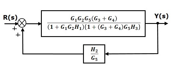
Step 5 − Use Rule 1 for blocks connected in series. The modified block diagram is shown in the following figure.
Step 6 − Use Rule 3 for blocks connected in feedback loop. The modified block diagram is shown in the following figure. This is the simplified block diagram.
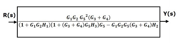
Therefore, the transfer function of the system is
$$\frac{Y(s)}{R(s)}=\frac{G_1G_2G_5^2(G_3+G_4)}{(1+G_1G_2H_1)\lbrace 1+(G_3+G_4)G_5H_3\rbrace G_5-G_1G_2G_5(G_3+G_4)H_2}$$
Note − Follow these steps in order to calculate the transfer function of the block diagram having multiple inputs.
Step 1 − Find the transfer function of block diagram by considering one input at a time and make the remaining inputs as zero.
Step 2 − Repeat step 1 for remaining inputs.
Step 3 − Get the overall transfer function by adding all those transfer functions.
The block diagram reduction process takes more time for complicated systems. Because, we have to draw the (partially simplified) block diagram after each step. So, to overcome this drawback, use signal flow graphs (representation).
In the next two chapters, we will discuss about the concepts related to signal flow graphs, i.e., how to represent signal flow graph from a given block diagram and calculation of transfer function just by using a gain formula without doing any reduction process.
