
- Control Systems - Home
- Control Systems - Introduction
- Control Systems - Feedback
- Mathematical Models
- Modelling of Mechanical Systems
- Electrical Analogies of Mechanical Systems
- Control Systems - Block Diagrams
- Block Diagram Algebra
- Block Diagram Reduction
- Signal Flow Graphs
- Mason's Gain Formula
- Time Response Analysis
- Response of the First Order System
- Response of Second Order System
- Time Domain Specifications
- Steady State Errors
- Control Systems - Stability
- Control Systems - Stability Analysis
- Control Systems - Root Locus
- Construction of Root Locus
- Frequency Response Analysis
- Control Systems - Bode Plots
- Construction of Bode Plots
- Control Systems - Polar Plots
- Control Systems - Nyquist Plots
- Control Systems - Compensators
- Control Systems - Controllers
- Control Systems - State Space Model
- State Space Analysis
Control Systems - Block Diagrams
Block diagrams consist of a single block or a combination of blocks. These are used to represent the control systems in pictorial form.
Basic Elements of Block Diagram
The basic elements of a block diagram are a block, the summing point and the take-off point. Let us consider the block diagram of a closed loop control system as shown in the following figure to identify these elements.
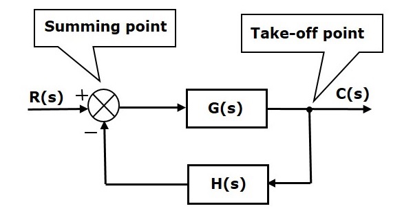
The above block diagram consists of two blocks having transfer functions G(s) and H(s). It is also having one summing point and one take-off point. Arrows indicate the direction of the flow of signals. Let us now discuss these elements one by one.
Block
The transfer function of a component is represented by a block. Block has single input and single output.
The following figure shows a block having input X(s), output Y(s) and the transfer function G(s).

Transfer Function,$G(s)=\frac{Y(s)}{X(s)}$
$$\Rightarrow Y(s)=G(s)X(s)$$
Output of the block is obtained by multiplying transfer function of the block with input.
Summing Point
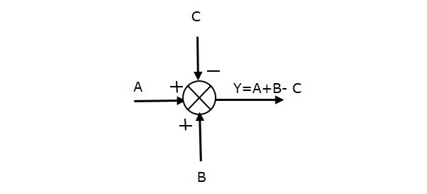
The summing point is represented with a circle having cross (X) inside it. It has two or more inputs and single output. It produces the algebraic sum of the inputs. It also performs the summation or subtraction or combination of summation and subtraction of the inputs based on the polarity of the inputs. Let us see these three operations one by one.
The following figure shows the summing point with two inputs (A, B) and one output (Y). Here, the inputs A and B have a positive sign. So, the summing point produces the output, Y as sum of A and B.
i.e.,Y = A + B.

The following figure shows the summing point with two inputs (A, B) and one output (Y). Here, the inputs A and B are having opposite signs, i.e., A is having positive sign and B is having negative sign. So, the summing point produces the output Y as the difference of A and B.
Y = A + (-B) = A - B.

The following figure shows the summing point with three inputs (A, B, C) and one output (Y). Here, the inputs A and B are having positive signs and C is having a negative sign. So, the summing point produces the output Y as
Y = A + B + (C) = A + B C.
Take-off Point
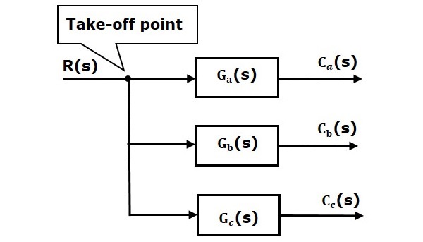
The take-off point is a point from which the same input signal can be passed through more than one branch. That means with the help of take-off point, we can apply the same input to one or more blocks, summing points.
In the following figure, the take-off point is used to connect the same input, R(s) to two more blocks.
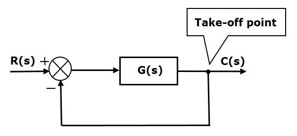
In the following figure, the take-off point is used to connect the output C(s), as one of the inputs to the summing point.
Block Diagram Representation of Electrical Systems
In this section, let us represent an electrical system with a block diagram. Electrical systems contain mainly three basic elements resistor, inductor and capacitor.
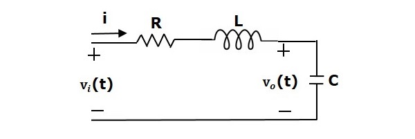
Consider a series of RLC circuit as shown in the following figure. Where, Vi(t) and Vo(t) are the input and output voltages. Let i(t) be the current passing through the circuit. This circuit is in time domain.
By applying the Laplace transform to this circuit, will get the circuit in s-domain. The circuit is as shown in the following figure.
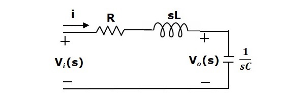
From the above circuit, we can write
$$I(s)=\frac{V_i(s)-V_o(s)}{R+sL}$$
$\Rightarrow I(s)=\left \{ \frac{1}{R+sL} \right \}\left \{ V_i(s)-V_o(s) \right \}$ (Equation 1)
$V_o(s)=\left ( \frac{1}{sC} \right )I(s)$ (Equation 2)
Let us now draw the block diagrams for these two equations individually. And then combine those block diagrams properly in order to get the overall block diagram of series of RLC Circuit (s-domain).
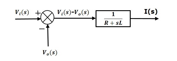
Equation 1 can be implemented with a block having the transfer function, $\frac{1}{R+sL}$. The input and output of this block are $\left \{ V_i(s)-V_o(s) \right \}$ and $I(s)$. We require a summing point to get $\left \{ V_i(s)-V_o(s) \right \}$. The block diagram of Equation 1 is shown in the following figure.
Equation 2 can be implemented with a block having transfer function, $\frac{1}{sC}$. The input and output of this block are $I(s)$ and $V_o(s)$. The block diagram of Equation 2 is shown in the following figure.

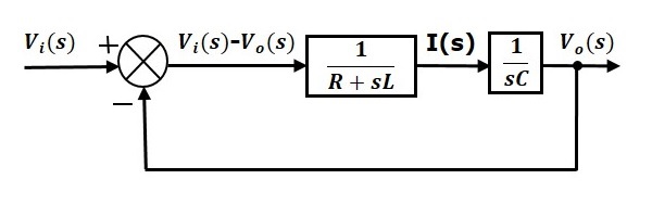
The overall block diagram of the series of RLC Circuit (s-domain) is shown in the following figure.
Similarly, you can draw the block diagram of any electrical circuit or system just by following this simple procedure.
Convert the time domain electrical circuit into an s-domain electrical circuit by applying Laplace transform.
Write down the equations for the current passing through all series branch elements and voltage across all shunt branches.
Draw the block diagrams for all the above equations individually.
Combine all these block diagrams properly in order to get the overall block diagram of the electrical circuit (s-domain).
