- Network Theory Tutorial
- Network Theory - Home
- Network Theory - Overview
- Example Problems
- Network Theory - Active Elements
- Network Theory - Passive Elements
- Network Theory - Kirchhoff’s Laws
- Electrical Quantity Division Principles
- Network Theory - Nodal Analysis
- Network Theory - Mesh Analysis
- Network Theory - Equivalent Circuits
- Equivalent Circuits Example Problem
- Delta to Star Conversion
- Star to Delta Conversion
- Network Theory - Network Topology
- Network Topology Matrices
- Superposition Theorem
- Thevenin’s Theorem
- Network Theory - Norton’s Theorem
- Maximum Power Transfer Theorem
- Response of DC Circuits
- Response of AC Circuits
- Network Theory - Series Resonance
- Parallel Resonance
- Network Theory - Coupled Circuits
- Two-Port Networks
- Two-Port Parameter Conversions
- Network Theory - Filters
- Network Theory Useful Resources
- Network Theory - Quick Guide
- Network Theory - Useful Resources
- Network Theory - Discussion
Network Theory - Kirchhoff’s Laws
Network elements can be either of active or passive type. Any electrical circuit or network contains one of these two types of network elements or a combination of both.
Now, let us discuss about the following two laws, which are popularly known as Kirchhoff’s laws.
- Kirchhoff’s Current Law
- Kirchhoff’s Voltage Law
Kirchhoff’s Current Law
Kirchhoff’s Current Law (KCL) states that the algebraic sum of currents leaving (or entering) a node is equal to zero.
A Node is a point where two or more circuit elements are connected to it. If only two circuit elements are connected to a node, then it is said to be simple node. If three or more circuit elements are connected to a node, then it is said to be Principal Node.
Mathematically, KCL can be represented as
$$\displaystyle\sum\limits_{m=1}^M I_m = 0$$
Where,
Im is the mth branch current leaving the node.
M is the number of branches that are connected to a node.
The above statement of KCL can also be expressed as "the algebraic sum of currents entering a node is equal to the algebraic sum of currents leaving a node". Let us verify this statement through the following example.
Example
Write KCL equation at node P of the following figure.
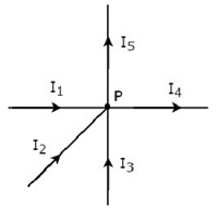
In the above figure, the branch currents I1, I2 and I3 are entering at node P. So, consider negative signs for these three currents.
In the above figure, the branch currents I4 and I5 are leaving from node P. So, consider positive signs for these two currents.
The KCL equation at node P will be
$$- I_1 - I_2 - I_3 + I_4 + I_5 = 0$$
$$\Rightarrow I_1 + I_2 + I_3 = I_4 + I_5$$
In the above equation, the left-hand side represents the sum of entering currents, whereas the right-hand side represents the sum of leaving currents.
In this tutorial, we will consider positive sign when the current leaves a node and negative sign when it enters a node. Similarly, you can consider negative sign when the current leaves a node and positive sign when it enters a node. In both cases, the result will be same.
Note − KCL is independent of the nature of network elements that are connected to a node.
Kirchhoff’s Voltage Law
Kirchhoff’s Voltage Law (KVL) states that the algebraic sum of voltages around a loop or mesh is equal to zero.
A Loop is a path that terminates at the same node where it started from. In contrast, a Mesh is a loop that doesn’t contain any other loops inside it.
Mathematically, KVL can be represented as
$$\displaystyle\sum\limits_{n=1}^N V_n = 0$$
Where,
Vn is the nth element’s voltage in a loop (mesh).
N is the number of network elements in the loop (mesh).
The above statement of KVL can also be expressed as "the algebraic sum of voltage sources is equal to the algebraic sum of voltage drops that are present in a loop." Let us verify this statement with the help of the following example.
Example
Write KVL equation around the loop of the following circuit.
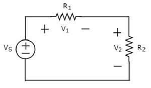
The above circuit diagram consists of a voltage source, VS in series with two resistors R1 and R2. The voltage drops across the resistors R1 and R2 are V1 and V2 respectively.
Apply KVL around the loop.
$$V_S - V_1 - V_2 = 0$$
$$\Rightarrow V_S = V_1 + V_2$$
In the above equation, the left-hand side term represents single voltage source VS. Whereas, the right-hand side represents the sum of voltage drops. In this example, we considered only one voltage source. That’s why the left-hand side contains only one term. If we consider multiple voltage sources, then the left side contains sum of voltage sources.
In this tutorial, we consider the sign of each element’s voltage as the polarity of the second terminal that is present while travelling around the loop. Similarly, you can consider the sign of each voltage as the polarity of the first terminal that is present while travelling around the loop. In both cases, the result will be same.
Note − KVL is independent of the nature of network elements that are present in a loop.