- Network Theory Tutorial
- Network Theory - Home
- Network Theory - Overview
- Example Problems
- Network Theory - Active Elements
- Network Theory - Passive Elements
- Network Theory - Kirchhoff’s Laws
- Electrical Quantity Division Principles
- Network Theory - Nodal Analysis
- Network Theory - Mesh Analysis
- Network Theory - Equivalent Circuits
- Equivalent Circuits Example Problem
- Delta to Star Conversion
- Star to Delta Conversion
- Network Theory - Network Topology
- Network Topology Matrices
- Superposition Theorem
- Thevenin’s Theorem
- Network Theory - Norton’s Theorem
- Maximum Power Transfer Theorem
- Response of DC Circuits
- Response of AC Circuits
- Network Theory - Series Resonance
- Parallel Resonance
- Network Theory - Coupled Circuits
- Two-Port Networks
- Two-Port Parameter Conversions
- Network Theory - Filters
- Network Theory Useful Resources
- Network Theory - Quick Guide
- Network Theory - Useful Resources
- Network Theory - Discussion
Network Theory - Norton’s Theorem
Norton’s theorem is similar to Thevenin’s theorem. It states that any two terminal linear network or circuit can be represented with an equivalent network or circuit, which consists of a current source in parallel with a resistor. It is known as Norton’s equivalent circuit. A linear circuit may contain independent sources, dependent sources and resistors.
If a circuit has multiple independent sources, dependent sources, and resistors, then the response in an element can be easily found by replacing the entire network to the left of that element with a Norton’s equivalent circuit.
The response in an element can be the voltage across that element, current flowing through that element or power dissipated across that element.
This concept is illustrated in following figures.
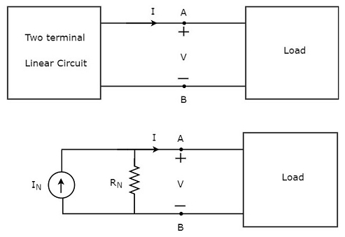
Norton’s equivalent circuit resembles a practical current source. Hence, it is having a current source in parallel with a resistor.
The current source present in the Norton’s equivalent circuit is called as Norton’s equivalent current or simply Norton’s current IN.
The resistor present in the Norton’s equivalent circuit is called as Norton’s equivalent resistor or simply Norton’s resistor RN.
Methods of Finding Norton’s Equivalent Circuit
There are three methods for finding a Norton’s equivalent circuit. Based on the type of sources that are present in the network, we can choose one of these three methods. Now, let us discuss these three methods one by one.
Method 1
Follow these steps in order to find the Norton’s equivalent circuit, when only the sources of independent type are present.
Step 1 − Consider the circuit diagram by opening the terminals with respect to which, the Norton’s equivalent circuit is to be found.
Step 2 − Find the Norton’s current IN by shorting the two opened terminals of the above circuit.
Step 3 − Find the Norton’s resistance RN across the open terminals of the circuit considered in Step1 by eliminating the independent sources present in it. Norton’s resistance RN will be same as that of Thevenin’s resistance RTh.
Step 4 − Draw the Norton’s equivalent circuit by connecting a Norton’s current IN in parallel with Norton’s resistance RN.
Now, we can find the response in an element that lies to the right side of Norton’s equivalent circuit.
Method 2
Follow these steps in order to find the Norton’s equivalent circuit, when the sources of both independent type and dependent type are present.
Step 1 − Consider the circuit diagram by opening the terminals with respect to which the Norton’s equivalent circuit is to be found.
Step 2 − Find the open circuit voltage VOC across the open terminals of the above circuit.
Step 3 − Find the Norton’s current IN by shorting the two opened terminals of the above circuit.
Step 4 − Find Norton’s resistance RN by using the following formula.
$$R_N = \frac{V_{OC}}{I_N}$$
Step 5 − Draw the Norton’s equivalent circuit by connecting a Norton’s current IN in parallel with Norton’s resistance RN.
Now, we can find the response in an element that lies to the right side of Norton’s equivalent circuit.
Method 3
This is an alternate method for finding a Norton’s equivalent circuit.
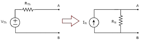
Step 1 − Find a Thevenin’s equivalent circuit between the desired two terminals. We know that it consists of a Thevenin’s voltage source, VTh and Thevenin’s resistor, RTh.
Step 2 − Apply source transformation technique to the above Thevenin’s equivalent circuit. We will get the Norton’s equivalent circuit. Here,
Norton’s current,
$$I_N = \frac{V_{Th}}{R_{Th}}$$
Norton’s resistance,
$$R_N = R_{Th}$$
This concept is illustrated in the following figure.
Now, we can find the response in an element by placing Norton’s equivalent circuit to the left of that element.
Note − Similarly, we can find the Thevenin’s equivalent circuit by finding a Norton’s equivalent circuit first and then apply source transformation technique to it. This concept is illustrated in the following figure.
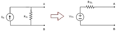
This is the Method 3 for finding a Thevenin’s equivalent circuit.
Example
Find the current flowing through 20 Ω resistor by first finding a Norton’s equivalent circuit to the left of terminals A and B.
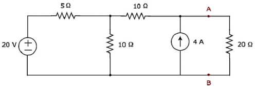
Let us solve this problem using Method 3.
Step 1 − In previous chapter, we calculated the Thevenin’s equivalent circuit to the left side of terminals A & B. We can use this circuit now. It is shown in the following figure.
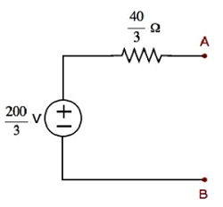
Here, Thevenin’s voltage, $V_{Th} = \frac{200}{3} V$ and Thevenin’s resistance, $R_{Th} = \frac{40}{3} \Omega$
Step 2 − Apply source transformation technique to the above Thevenin’s equivalent circuit. Substitute the values of VTh and RTh in the following formula of Norton’s current.
$$I_N = \frac{V_{Th}}{R_{Th}}$$
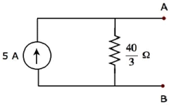
$$I_N = \frac{\frac{200}{3}}{\frac{40}{3}} = 5A$$
Therefore, Norton’s current IN is 5 A.
We know that Norton’s resistance, RN is same as that of Thevenin’s resistance RTh.
$$\mathbf {R_N = \frac{40}{3} \Omega}$$
The Norton’s equivalent circuit corresponding to the above Thevenin’s equivalent circuit is shown in the following figure.
Now, place the Norton’s equivalent circuit to the left of the terminals A & B of the given circuit.
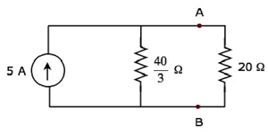
By using current division principle, the current flowing through the 20 Ω resistor will be
$$I_{20 \Omega} = 5 \lgroup \frac{\frac{40}{3}}{\frac{40}{3} + 20} \rgroup$$
$$I_{20 \Omega} = 5 \lgroup \frac{40}{100} \rgroup = 2A$$
Therefore, the current flowing through the 20 Ω resistor is 2 A.