- Network Theory Tutorial
- Network Theory - Home
- Network Theory - Overview
- Example Problems
- Network Theory - Active Elements
- Network Theory - Passive Elements
- Network Theory - Kirchhoff’s Laws
- Electrical Quantity Division Principles
- Network Theory - Nodal Analysis
- Network Theory - Mesh Analysis
- Network Theory - Equivalent Circuits
- Equivalent Circuits Example Problem
- Delta to Star Conversion
- Star to Delta Conversion
- Network Theory - Network Topology
- Network Topology Matrices
- Superposition Theorem
- Thevenin’s Theorem
- Network Theory - Norton’s Theorem
- Maximum Power Transfer Theorem
- Response of DC Circuits
- Response of AC Circuits
- Network Theory - Series Resonance
- Parallel Resonance
- Network Theory - Coupled Circuits
- Two-Port Networks
- Two-Port Parameter Conversions
- Network Theory - Filters
- Network Theory Useful Resources
- Network Theory - Quick Guide
- Network Theory - Useful Resources
- Network Theory - Discussion
Network Theory - Response of DC Circuits
If the output of an electric circuit for an input varies with respect to time, then it is called as time response. The time response consists of following two parts.
- Transient Response
- Steady state Response
In this chapter, first let us discuss about these two responses and then observe these two responses in a series RL circuit, when it is excited by a DC voltage source.
Transient Response
After applying an input to an electric circuit, the output takes certain time to reach steady state. So, the output will be in transient state till it goes to a steady state. Therefore, the response of the electric circuit during the transient state is known as transient response.
The transient response will be zero for large values of ‘t’. Ideally, this value of ‘t’ should be infinity. But, practically five time constants are sufficient.
Presence or Absence of Transients
Transients occur in the response due to sudden change in the sources that are applied to the electric circuit and / or due to switching action. There are two possible switching actions. Those are opening switch and closing switch.
The transient part will not present in the response of an electrical circuit or network, if it contains only resistances. Because resistor is having the ability to adjust any amount of voltage and current.
The transient part occurs in the response of an electrical circuit or network due to the presence of energy storing elements such as inductor and capacitor. Because they can’t change the energy stored in those elements instantly.
Inductor Behavior
Assume the switching action takes place at t = 0. Inductor current does not change instantaneously, when the switching action takes place. That means, the value of inductor current just after the switching action will be same as that of just before the switching action.
Mathematically, it can be represented as
$$i_L (0^+) = i_L (0^-)$$
Capacitor Behavior
The capacitor voltage does not change instantaneously similar to the inductor current, when the switching action takes place. That means, the value of capacitor voltage just after the switching action will be same as that of just before the switching action.
Mathematically, it can be represented as
$$v_c (0^+) = v_c (0^-)$$
Steady state Response
The part of the time response that remains even after the transient response has become zero value for large values of ‘t’ is known as steady state response. This means, there won’t be any transient part in the response during steady state.
Inductor Behavior
If the independent source is connected to the electric circuit or network having one or more inductors and resistors (optional) for a long time, then that electric circuit or network is said to be in steady state. Therefore, the energy stored in the inductor(s) of that electric circuit is of maximum and constant.
Mathematically, it can be represented as
$W_L = \frac{L {i_L}^2}{2} = $ Maximum & constant
$\Rightarrow i_L = $ Maximum & constant
Therefore, inductor acts as a constant current source in steady state.
The voltage across inductor will be
$$V_L = L \frac{di_{L}}{dt} = 0V$$
So, the inductor acts as a short circuit in steady state.
Capacitor Behavior
If the independent source is connected to the electric circuit or network having one or more capacitors and resistors (optional) for a long time, then that electric circuit or network is said to be in steady state. Therefore, the energy stored in the capacitor(s) of that electric circuit is of maximum and constant.
Mathematically, it can be represented as
$W_c = \frac{C{v_c}^2}{2} = $ Maximum & constant
$\Rightarrow v_c = $Maximum & constant
Therefore, capacitor acts as a constant voltage source in steady state.
The current flowing through the capacitor will be
$$i_c = C\frac{dv_c}{dt} = 0A$$
So, the capacitor acts as an open circuit in steady state.
Finding the Response of Series RL Circuit
Consider the following series RL circuit diagram.
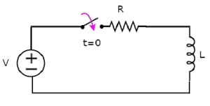
In the above circuit, the switch was kept open up to t = 0 and it was closed at t = 0. So, the DC voltage source having V volts is not connected to the series RL circuit up to this instant. Therefore, there is no initial current flows through inductor.
The circuit diagram, when the switch is in closed position is shown in the following figure.
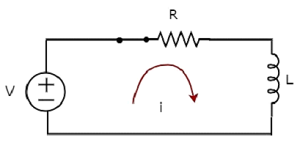
Now, the current i flows in the entire circuit, since the DC voltage source having V volts is connected to the series RL circuit.
Now, apply KVL around the loop.
$$V = Ri + L \frac{di}{dt}$$
$\frac{di}{dt} + \lgroup \frac{R}{L} \rgroup i = \frac{V}{L}$Equation 1
The above equation is a first order differential equation and it is in the form of
$\frac{dy}{dt} + Py = Q$Equation 2
By comparing Equation 1 and Equation 2, we will get the following relations.
$$x = t$$
$$y = i$$
$$P = \frac{R}{L}$$
$$Q = \frac{V}{L}$$
The solution of Equation 2 will be
$ye^{\int p dx} = \int Q e^{\int p dx} dx + k$Equation 3
Where, k is the constant.
Substitute, the values of x, y, P & Q in Equation 3.
$ie^{\int {\lgroup \frac{R}{L} \rgroup}dt} = \int (\frac{V}{L}) \lgroup e^{\int {\lgroup \frac{R}{L} \rgroup}dt} \rgroup dt + k$
$\Rightarrow ie^{\lgroup \frac{R}{L} \rgroup t} = \frac{V}{L} \int e^{\lgroup \frac{R}{L} \rgroup t} dt + k$
$\Rightarrow ie^{\lgroup \frac{R}{L} \rgroup t} = \frac{V}{L} \lbrace \frac{e^{\lgroup \frac{R}{L} \rgroup}t}{\frac{R}{L}} \rbrace + k$
$\Rightarrow i = \frac{V}{R} + k e^{-\lgroup \frac{R}{L} \rgroup}t$Equation 4
We know that there is no initial current in the circuit. Hence, substitute, t = 0 and 𝑖 = 0 in Equation 4 in order to find the value of the constant k.
$$0 = \frac{V}{R} + ke^{-\lgroup \frac{R}{L} \rgroup(0)}$$
$$0 = \frac{V}{R} + k(1)$$
$$k = - \frac{V}{R}$$
Substitute, the value of k in Equation 4.
$$i = \frac{V}{R} + \lgroup - \frac{V}{R} \rgroup e^{-\lgroup \frac{R}{L} \rgroup t}$$
$$i = \frac{V}{R} - \frac{V}{R}e^{-\lgroup \frac{R}{L} \rgroup t}$$
Therefore, the current flowing through the circuit is
$i = - \frac{V}{R}e^{-\lgroup \frac{R}{L} \rgroup t} + \frac{V}{R}$Equation 5
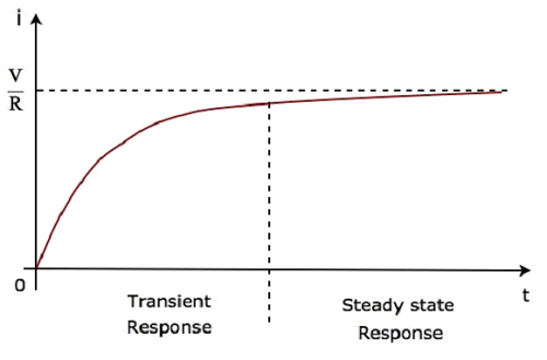
So, the response of the series RL circuit, when it is excited by a DC voltage source, has the following two terms.
The first term $-\frac{V}{R}e^{-\lgroup \frac{R}{L} \rgroup t}$ corresponds with the transient response.
The second term $\frac{V}{R}$ corresponds with the steady state response. These two responses are shown in the following figure.
We can re-write the Equation 5 as follows −
$i = \frac{V}{R} \lgroup 1 - e^{-\lgroup \frac{R}{L} \rgroup t} \rgroup$
$\Rightarrow i = \frac{V}{R} \lgroup 1 - e^{-\lgroup \frac{t}{\tau} \rgroup} \rgroup$Equation 6
Where, τ is the time constant and its value is equal to $\frac{L}{R}$.
Both Equation 5 and Equation 6 are same. But, we can easily understand the above waveform of current flowing through the circuit from Equation 6 by substituting a few values of t like 0, τ, 2τ, 5τ, etc.
In the above waveform of current flowing through the circuit, the transient response will present up to five time constants from zero, whereas the steady state response will present from five time constants onwards.