- Network Theory Tutorial
- Network Theory - Home
- Network Theory - Overview
- Example Problems
- Network Theory - Active Elements
- Network Theory - Passive Elements
- Network Theory - Kirchhoff’s Laws
- Electrical Quantity Division Principles
- Network Theory - Nodal Analysis
- Network Theory - Mesh Analysis
- Network Theory - Equivalent Circuits
- Equivalent Circuits Example Problem
- Delta to Star Conversion
- Star to Delta Conversion
- Network Theory - Network Topology
- Network Topology Matrices
- Superposition Theorem
- Thevenin’s Theorem
- Network Theory - Norton’s Theorem
- Maximum Power Transfer Theorem
- Response of DC Circuits
- Response of AC Circuits
- Network Theory - Series Resonance
- Parallel Resonance
- Network Theory - Coupled Circuits
- Two-Port Networks
- Two-Port Parameter Conversions
- Network Theory - Filters
- Network Theory Useful Resources
- Network Theory - Quick Guide
- Network Theory - Useful Resources
- Network Theory - Discussion
Electrical Quantity Division Principles
In this chapter, let us discuss about the following two division principles of electrical quantities.
- Current Division Principle
- Voltage Division Principle
Current Division Principle
When two or more passive elements are connected in parallel, the amount of current that flows through each element gets divided (shared) among themselves from the current that is entering the node.
Consider the following circuit diagram.
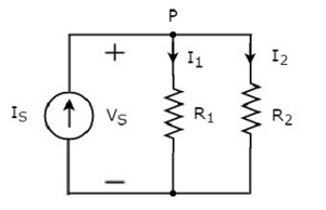
The above circuit diagram consists of an input current source IS in parallel with two resistors R1 and R2. The voltage across each element is VS. The currents flowing through the resistors R1 and R2 are I1 and I2 respectively.
The KCL equation at node P will be
$$I_S = I_1 + I_2$$
Substitute $I_1 = \frac{V_S}{R_1}$ and $I_2 = \frac{V_S}{R_2}$ in the above equation.
$$I_S = \frac{V_S}{R_1} + \frac{V_S}{R_2} = V_S \lgroup \frac {R_2 + R_1 }{R_1 R_2} \rgroup$$
$$\Rightarrow V_S = I_S \lgroup \frac{R_1R_2}{R_1 + R_2} \rgroup$$
Substitute the value of VS in $I_1 = \frac{V_S}{R_1}$.
$$I_1 = \frac{I_S}{R_1}\lgroup \frac{R_1 R_2}{R_1 + R_2} \rgroup$$
$$\Rightarrow I_1 = I_S\lgroup \frac{R_2}{R_1 + R_2} \rgroup$$
Substitute the value of VS in $I_2 = \frac{V_S}{R_2}$.
$$I_2 = \frac{I_S}{R_2} \lgroup \frac{R_1 R_2}{R_1 + R_2} \rgroup$$
$$\Rightarrow I_2 = I_S \lgroup \frac{R_1}{R_1 + R_2} \rgroup$$
From equations of I1 and I2, we can generalize that the current flowing through any passive element can be found by using the following formula.
$$I_N = I_S \lgroup \frac{Z_1\rVert Z_2 \rVert...\rVert Z_{N-1}}{Z_1 + Z_2 + ... + Z_N}\rgroup$$
This is known as current division principle and it is applicable, when two or more passive elements are connected in parallel and only one current enters the node.
Where,
IN is the current flowing through the passive element of Nth branch.
IS is the input current, which enters the node.
Z1, Z2, …,ZN are the impedances of 1st branch, 2nd branch, …, Nth branch respectively.
Voltage Division Principle
When two or more passive elements are connected in series, the amount of voltage present across each element gets divided (shared) among themselves from the voltage that is available across that entire combination.
Consider the following circuit diagram.
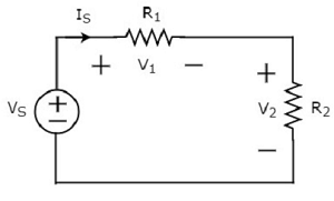
The above circuit diagram consists of a voltage source, VS in series with two resistors R1 and R2. The current flowing through these elements is IS. The voltage drops across the resistors R1 and R2 are V1 and V2 respectively.
The KVL equation around the loop will be
$$V_S = V_1 + V_2$$
Substitute V1 = IS R1 and V2 = IS R2 in the above equation
$$V_S = I_S R_1 + I_S R_2 = I_S(R_1 + R_2)$$
$$I_S = \frac{V_S}{R_1 + R_2}$$
Substitute the value of IS in V1 = IS R1.
$$V_1 = \lgroup \frac {V_S}{R_1 + R_2} \rgroup R_1$$
$$\Rightarrow V_1 = V_S \lgroup \frac {R_1}{R_1 + R_2} \rgroup$$
Substitute the value of IS in V2 = IS R2.
$$V_2 = \lgroup \frac {V_S}{R_1 + R_2} \rgroup R_2$$
$$\Rightarrow V_2 = V_S \lgroup \frac {R_2}{R_1 + R_2} \rgroup$$
From equations of V1 and V2, we can generalize that the voltage across any passive element can be found by using the following formula.
$$V_N = V_S \lgroup \frac {Z_N}{Z_1 + Z_2 +....+ Z_N}\rgroup$$
This is known as voltage division principle and it is applicable, when two or more passive elements are connected in series and only one voltage available across the entire combination.
Where,
VN is the voltage across Nth passive element.
VS is the input voltage, which is present across the entire combination of series passive elements.
Z1,Z2, …,Z3 are the impedances of 1st passive element, 2nd passive element, …, Nth passive element respectively.