- Network Theory Tutorial
- Network Theory - Home
- Network Theory - Overview
- Example Problems
- Network Theory - Active Elements
- Network Theory - Passive Elements
- Network Theory - Kirchhoff’s Laws
- Electrical Quantity Division Principles
- Network Theory - Nodal Analysis
- Network Theory - Mesh Analysis
- Network Theory - Equivalent Circuits
- Equivalent Circuits Example Problem
- Delta to Star Conversion
- Star to Delta Conversion
- Network Theory - Network Topology
- Network Topology Matrices
- Superposition Theorem
- Thevenin’s Theorem
- Network Theory - Norton’s Theorem
- Maximum Power Transfer Theorem
- Response of DC Circuits
- Response of AC Circuits
- Network Theory - Series Resonance
- Parallel Resonance
- Network Theory - Coupled Circuits
- Two-Port Networks
- Two-Port Parameter Conversions
- Network Theory - Filters
- Network Theory Useful Resources
- Network Theory - Quick Guide
- Network Theory - Useful Resources
- Network Theory - Discussion
Network Theory - Equivalent Circuits
If a circuit consists of two or more similar passive elements and are connected in exclusively of series type or parallel type, then we can replace them with a single equivalent passive element. Hence, this circuit is called as an equivalent circuit.
In this chapter, let us discuss about the following two equivalent circuits.
- Series Equivalent Circuit
- Parallel Equivalent Circuit
Series Equivalent Circuit
If similar passive elements are connected in series, then the same current will flow through all these elements. But, the voltage gets divided across each element.
Consider the following circuit diagram.
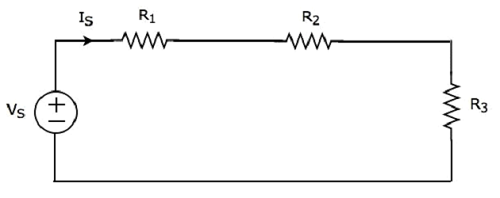
It has a single voltage source (VS) and three resistors having resistances of R1, R2 and R3. All these elements are connected in series. The current IS flows through all these elements.
The above circuit has only one mesh. The KVL equation around this mesh is
$$V_S = V_1 + V_2 + V_3$$
Substitute $V_1 = I_S R_1, \: V_2 = I_S R_2$ and $V_3 = I_S R_3$ in the above equation.
$$V_S = I_S R_1 + I_S R_2 + I_S R_3$$
$$\Rightarrow V_S = I_S(R_1 + R_2 + R_3)$$
The above equation is in the form of $V_S = I_S R_{Eq}$ where,
$$R_{Eq} = R_1 + R_2 + R_3$$
The equivalent circuit diagram of the given circuit is shown in the following figure.
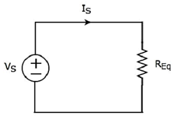
That means, if multiple resistors are connected in series, then we can replace them with an equivalent resistor. The resistance of this equivalent resistor is equal to sum of the resistances of all those multiple resistors.
Note 1 − If ‘N’ inductors having inductances of L1, L2, ..., LN are connected in series, then the equivalent inductance will be
$$L_{Eq} = L_1 + L_2 + ... + L_N$$
Note 2 − If ‘N’ capacitors having capacitances of C1, C2, ..., CN are connected in series, then the equivalent capacitance will be
$$\frac{1}{C_{Eq}} = \frac{1}{C_1} + \frac{1}{C_2} + ... + \frac{1}{C_N}$$
Parallel Equivalent Circuit
If similar passive elements are connected in parallel, then the same voltage will be maintained across each element. But, the current flowing through each element gets divided.
Consider the following circuit diagram.
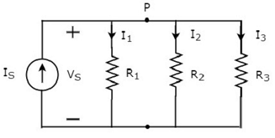
It has a single current source (IS) and three resistors having resistances of R1, R2, and R3. All these elements are connected in parallel. The voltage (VS) is available across all these elements.
The above circuit has only one principal node (P) except the Ground node. The KCL equation at this principal node (P) is
$$I_S = I_1 + I_2 + I_3$$
Substitute $I_1 = \frac{V_S}{R_1}, \: I_2 = \frac{V_S}{R_2}$ and $I_3 = \frac{V_S}{R_3}$ in the above equation.
$$I_S = \frac{V_S}{R_1} + \frac{V_S}{R_2} + \frac{V_S}{R_3}$$
$$\Rightarrow I_S = V_S \lgroup \frac{1}{R_1} + \frac{1}{R_2} + \frac{1}{R_3} \rgroup$$
$$\Rightarrow V_S = I_S\left [ \frac{1}{\lgroup \frac{1}{R_1} + \frac{1}{R_2} + \frac{1}{R_3} \rgroup} \right ]$$
The above equation is in the form of VS = ISREq where,
$$R_{Eq} = \frac{1}{\lgroup \frac{1}{R_1} + \frac{1}{R_2} + \frac{1}{R_3} \rgroup}$$
$$\frac{1}{R_{Eq}} = \frac{1}{R_1} + \frac{1}{R_2} + \frac{1}{R_3}$$
The equivalent circuit diagram of the given circuit is shown in the following figure.
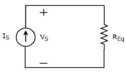
That means, if multiple resistors are connected in parallel, then we can replace them with an equivalent resistor. The resistance of this equivalent resistor is equal to the reciprocal of sum of reciprocal of each resistance of all those multiple resistors.
Note 1 − If ‘N’ inductors having inductances of L1, L2, ..., LN are connected in parallel, then the equivalent inductance will be
$$\frac{1}{L_{Eq}} = \frac{1}{L_1} + \frac{1}{L_2} + ... + \frac{1}{L_N}$$
Note 2 − If ‘N’ capacitors having capacitances of C1, C2, ..., CN are connected in parallel, then the equivalent capacitance will be
$$C_{Eq} = C_1 + C_2 + ... + C_N$$