
Article Categories
- All Categories
-
 Data Structure
-
 Networking
-
 RDBMS
RDBMS
-
 Operating System
-
 Java
Java
-
 MS Excel
-
 iOS
iOS
-
 HTML
HTML
-
 CSS
CSS
-
 Android
-
 Python
-
 C Programming
-
 C++
C++
-
 C#
C#
-
 MongoDB
-
 MySQL
MySQL
-
 Javascript
-
 PHP
PHP
-
 Economics & Finance
What is Pipelining in Computer Architecture?
Pipelining defines the temporal overlapping of processing. Pipelines are emptiness greater than assembly lines in computing that can be used either for instruction processing or, in a more general method, for executing any complex operations. It can be used efficiently only for a sequence of the same task, much similar to assembly lines.
A basic pipeline processes a sequence of tasks, including instructions, as per the following principle of operation −
Each task is subdivided into multiple successive subtasks as shown in the figure. For instance, the execution of register-register instructions can be broken down into instruction fetch, decode, execute, and writeback.
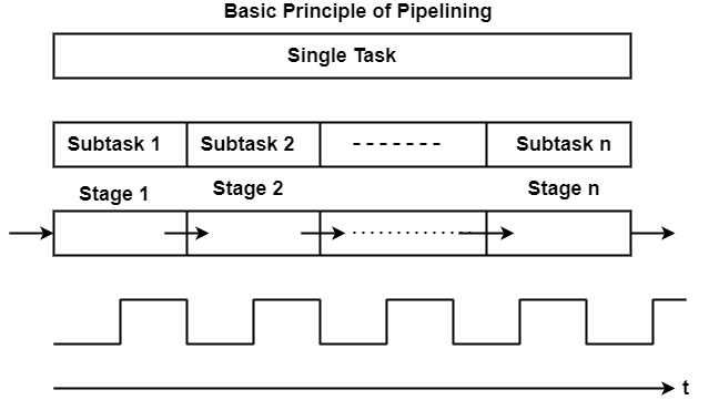
A pipeline phase related to each subtask executes the needed operations.
A similar amount of time is accessible in each stage for implementing the needed subtask.
All pipeline stages work just as an assembly line that is, receiving their input generally from the previous stage and transferring their output to the next stage.
Finally, it can consider the basic pipeline operates clocked, in other words synchronously. This defines that each stage gets a new input at the beginning of the clock cycle, each stage has a single clock cycle available for implementing the needed operations, and each stage produces the result to the next stage by the starting of the subsequent clock cycle.
Advantages of Pipelining
The cycle time of the processor is decreased. It can improve the instruction throughput. Pipelining doesn't lower the time it takes to do an instruction. Rather than, it can raise the multiple instructions that can be processed together ("at once") and lower the delay between completed instructions (known as 'throughput').
If pipelining is used, the CPU Arithmetic logic unit (ALU) can be designed quicker, but more complex.
Pipelining increases execution over an un-pipelined core by an element of the multiple stages (considering the clock frequency also increases by a similar factor) and the code is optimal for pipeline execution.
Pipelined CPUs frequently work at a higher clock frequency than the RAM clock frequency, (as of 2008 technologies, RAMs operate at a low frequency correlated to CPUs frequencies) increasing the computer’s global implementation.

32K+ Views
