
Article Categories
- All Categories
-
 Data Structure
-
 Networking
-
 RDBMS
RDBMS
-
 Operating System
-
 Java
Java
-
 MS Excel
-
 iOS
iOS
-
 HTML
HTML
-
 CSS
CSS
-
 Android
-
 Python
-
 C Programming
-
 C++
C++
-
 C#
C#
-
 MongoDB
-
 MySQL
MySQL
-
 Javascript
-
 PHP
PHP
-
 Economics & Finance
What is the Format of Microinstruction in Computer Architecture?
A microinstruction format includes 20 bits in total. They are divided into four elements as displayed in the figure.
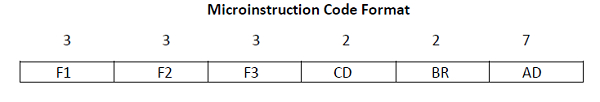
F1, F2, F3 are the micro-operation fields. They determine micro-operations for the computer.
CD is the condition for branching. They choose the status bit conditions.
BR is the branch field. It determines the type of branch.
AD is the address field. It includes the address field whose length is 7 bits.
The micro-operations are divided into three fields of three bits each. These three bits can define seven different micro-operations. In total there are 21 operations as displayed in the table.
Symbols with their Binary Code for Microinstruction Fields
| Name: | Code | Symbol | |
|---|---|---|---|
| F1 | 000 | None | NOP |
| 001 | AC ← AC + DR | ADD | |
| 010 | AC ← 0 | CLRAC | |
| 011 | AC ← AC + 1 | INCAC | |
| 100 | AC ← DR | DRTAC | |
| 101 | AR ← DR(0 − 10) | DRTAR | |
| 110 | AR ← PC | PCTAR | |
| 111 | AC ← AC + DR | WRITE | |
| F2 | 000 | None | NOP |
| 001 | AC ← AC + DR | SUB | |
| 010 | AC ← AC ∨ DR | OR | |
| 011 | AC ← AC ∧ DR | AND | |
| 100 | DR ← M[AR] | READ | |
| 101 | DR ← AC | ACTDR | |
| 110 | DR ← DR + 1 | INCDR | |
| 111 | DR(0 − 10) ← PC | PCTDR | |
| F3 | 000 | None | NOP |
| 001 | AC ← AC ⊕ DR | XOR | |
| 010 | AC ← AC′ | COM | |
| 011 | AC ← shl AC | SHL | |
| 100 | AC ← shr AC | SHR | |
| 101 | PC ← PC + 1 | INCPC | |
| 110 | PC ← AR | ARTPC | |
| 111 | DR(0 − 10) ← PC | Reserved |
As shown in the table, each microinstruction can have only three micro-operations, one from each field. If it uses less than three, it will result in more than one operation using the no operation binary code.
Condition Field
A condition field includes 2 bits. They are encoded to define four status bit conditions. As stated in the table, the first condition is always a 1, with CD = 0. The symbol that can indicate this condition is ‘U’. The table displays the multiple condition fields and their summary in an easy manner.
Condition Field Symbols and Descriptions
| Condition | Symbol | Comments | |
|---|---|---|---|
| 00 | Always = 1 | U | Unconditional Branch |
| 01 | DR (15) | I | Indirect address bit |
| 10 | AC (15) | S | Sign bit of AC |
| 11 | AC = 0 | Z | Zero value in AC |
As shown in the table, when condition 00 is connected with BR (branch) field, it results in an unconditional branch operation. Then the execution is read from memory the indirect bit I is accessible from bit 15 of DR. The status of the next bit is supported by the AC sign bit. If all the bits in AC are 1, then it is indicated as Z (its binary variable whose value is 1). The symbols U, I, S, and Z can indicate status bits while writing microprograms.
Branch Field
The BR (branch) field includes 2 bits. It can be used by connecting with the AD (address) field. The reason for connecting with the AD field is to select the address for the next microinstruction. The table illustrates the various branch fields and their functions.
Branch Field Symbols and Descriptions
| BR | Symbol | Comments |
| 00 | JMP | CAR ←AD if condition = 1 |
| CAR←CAR + 1 if condition = 0 | ||
| 01 | CALL | CAR ←AD , SBR ← CAR +1, if condition = 1 |
| CAR←CAR + 1 if condition = 0 | ||
| 10 | RET | CAR ←SBR (Return from subroutine) |
| 11 | MAP | CAR(2-5) ←DR(11-14), CAR(0,1,6) ←0 |
As shown in the table, when BR = 00, a JMP operation is implemented and when BR = 01, a subroutine is called. The only difference between the two instructions is that when the microinstruction is saved, the return address is saved in the Subroutine Register (SBR).
These two operations are dependent on the CD field values. When the status bit condition of the CD field is defined as 1, the address that is next in order is transferred to CAR. Else, it gets incremented. If the instruction needs to return from the subroutine, its BR field is determined as 10.
This results in the transfer of the return address from SBR to CAR. The opcode bits of instruction can be mapped with an address for CAR if the BR field is 11. They are present in DR (11 - 14) after instruction is read from memory. The last two conditions in the BR fields are not dependent on the CD and AD field values.

39K+ Views
