
Article Categories
- All Categories
-
 Data Structure
-
 Networking
-
 RDBMS
RDBMS
-
 Operating System
-
 Java
Java
-
 MS Excel
-
 iOS
iOS
-
 HTML
HTML
-
 CSS
CSS
-
 Android
-
 Python
-
 C Programming
-
 C++
C++
-
 C#
C#
-
 MongoDB
-
 MySQL
MySQL
-
 Javascript
-
 PHP
PHP
-
 Economics & Finance
What is Instruction Pipeline in Computer Architecture?
An instruction pipeline reads consecutive instructions from memory while in the other segments the previous instructions are being implemented. Pipeline processing appears both in the data flow and in the instruction stream. This leads to the overlapping of the fetch and executes the instruction and hence simultaneous operations are performed.
There is one possible more event associated with such a design is that instruction can generate a branch out of a sequence. In this method, the pipeline is clear and all the instructions that have previously been read from memory after the branch instruction should be rejected.
A computer can be constructed to support a two-segment unit, with an instruction fetch unit and an instruction execution unit. Using a first-in, first-out (FIFO) buffer the instruction fetch segment is implemented.
This is a method of a unit forming a queue instead of a stack. When the implementation unit is not creating the memory, the control increments the program counter and helps its address value to read consecutive instructions from memory.
The instructions are inserted into the FIFO buffer so that the implementation appears on a FIFO basis. Therefore an instruction flow can be located in a queue to wait for decoding and phasing by the implementation segment.
Therefore, the instruction stream queuing structure offers an effective approach for decreasing the average access time for memory to read instructions. Whenever there is an area in the FIFO buffer, the control unit starts the next instruction fetch step.
The buffer facilitates as a queue from which regulate then derive the instructions for the implementation unit.
A device with complex instructions needed other steps in addition to the fetch and execute to process an instruction thoroughly. In this method, the device requires to process each instruction with the following series of steps.
- It can fetch instruction from memory.
- It can decode instruction.
- It can calculate effective addresses.
- It can fetch operands from memory.
- It can execute the instruction.
- It can save the result in a suitable place.
Multiple segments can take different time durations to work on the incoming data. This can avoid the instruction pipeline from working at its maximum speed. Few segments are skipped for specific operations.
The figure shows an example of instruction pipelining.
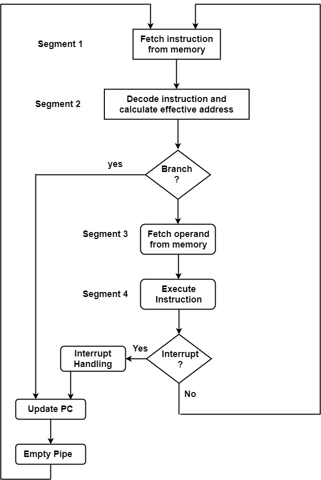
Segment 1
The instruction fetch segment can be executed using a first-in, first-out (FIFO) buffer.
Segment 2
The instruction fetched from memory is decoded in the second segment. The effective address is computed in an independent arithmetic circuit.
Segment 3
An operand from memory is fetched in the third segment.
Segment 4
The instructions are finally implemented in the final segment of the pipeline organization.

25K+ Views
