- Home
- Introduction
- Performance Characteristics
- Measurement Errors
- Measuring Instruments
- DC Voltmeters
- AC Voltmeters
- Other AC Voltmeters
- DC Ammeters
- AC Ammeter
- OHMMeters
- MultiMeter
- Signal Generators
- Wave Analyzers
- Spectrum Analyzers
- Basics of Oscilloscopes
- Special Purpose Oscilloscopes
- Lissajous Figures
- CRO Probes
- Bridges
- DC Bridges
- AC Bridges
- Other AC Bridges
- Transducers
- Active Transducers
- Passive Transducers
- Measurement Of Displacement
- Data Acquisition Systems
Measurement Of Displacement
The physical quantities such as displacement, velocity, force, temperature & etc. are all non-electrical quantities. active transducer converts the physical quantity into an electrical signal. Whereas, passive transducer converts the physical quantity into the variation in passive element.
So, based on the requirement we can choose either active transducer or passive transducer. In this chapter, let us discuss how to measure displacement by using a passive transducer. If a body that moves from one point to another point in a straight line, then the length between those two points is called displacement.
We have the following three passive transducers
- Resistive Transducer
- Inductive Transducer
- Capacitive Transducer
Now, let us discuss about the measurement of displacement with these three passive transducers one by one.
Measurement of Displacement using Resistive Transducer
The circuit diagram of resistive transducer, which is used to measure displacement is shown in below figure.
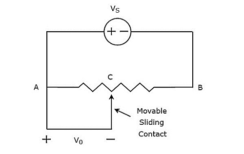
The above circuit consists of a potentiometer and a voltage source, $V_{S}$. We can say that these two are connected in parallel with respect to the points A & B. Potentiometer has a sliding contact, which can be varied. So, the point C is a variable one. In above circuit, the output voltage, $V_{0}$ is measured across the points A & C.
Mathematically, the relation between the voltages and distances can be represented as
$$\frac{V_{0}}{V_{S}}=\frac{AC}{AB}$$
Therefore, we should connect the body whose displacement is to be measured to the sliding contact. So, whenever the body moves in a straight line, the point C also varies. Due to this, the output voltage, $V_{0}$ also changes accordingly.
In this case, we can find the displacement by measuring the output voltage, $V_{0}$.
Measurement of Displacement using Inductive Transducer
The circuit diagram of inductive transducer, which is used to measure displacement is shown in below figure.
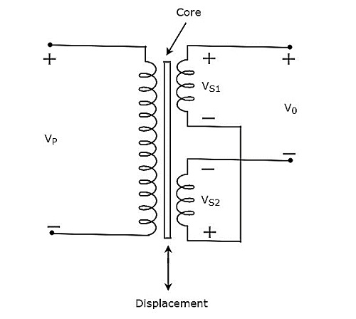
The transformer present in above circuit has a primary winding and two secondary windings. Here, the ending points of two secondary windings are joined together. So, we can say that these two secondary windings are connected in series opposition.
The voltage, $V_{P}$ is applied across the primary winding of transformer. Let, the voltage developed across each secondary winding is 1 and 2. The output voltage, $V_{0}$ is taken across the starting points of two secondary windings.
Mathematically, the output voltage, 0 can be written as
$$V_{0}= V_{S1}-V_{S2}$$
The transformer present in above circuit is called differential transformer, since it produces an output voltage, which is the difference between $V_{S1}$ and $V_{S2}$.
If the core is at central position, then the output voltage, $V_{0}$ will be equal to zero. Because, the respective magnitudes & phases of $V_{S1}$ and $V_{S2}$ are same.
If the core is not at central position, then the output voltage, $V_{0}$ will be having some magnitude & phase. Because, the respective magnitudes & phases of $V_{S1}$ and $V_{S2}$ are not equal.
Therefore, we should connect the body whose displacement is to be measured to the central core. So, whenever the body moves in a straight line, the central position of the core varies. Due to this, the output voltage, $V_{0}$ also changes accordingly.
In this case, we can find the displacement by measuring the output voltage, $V_{0}$. The magnitude & phase of output voltage, $V_{0}$ represents the displacement of the body & its direction respectively.
Measurement of Displacement using Capacitive Transducer
The circuit diagram of capacitive transducer, which is used to measure displacement is shown in below figure.
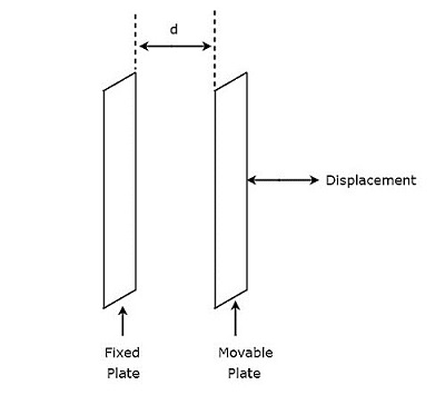
The capacitor, which is present in above circuit has two parallel plates. Among which, one plate is fixed and the other plate is a movable one. Due to this, the spacing between these two plates will also vary. the value of capacitance changes as the spacing between two plates of capacitor changes.
Therefore, we should connect the body whose displacement is to be measured to the movable plate of a capacitor. So, whenever the body moves in a straight line, the spacing between the two plates of capacitor varies. Due to this, the capacitance value changes.
