- Home
- Introduction
- Performance Characteristics
- Measurement Errors
- Measuring Instruments
- DC Voltmeters
- AC Voltmeters
- Other AC Voltmeters
- DC Ammeters
- AC Ammeter
- OHMMeters
- MultiMeter
- Signal Generators
- Wave Analyzers
- Spectrum Analyzers
- Basics of Oscilloscopes
- Special Purpose Oscilloscopes
- Lissajous Figures
- CRO Probes
- Bridges
- DC Bridges
- AC Bridges
- Other AC Bridges
- Transducers
- Active Transducers
- Passive Transducers
- Measurement Of Displacement
- Data Acquisition Systems
Active Transducers
Active transducer is a transducer, which converts the non-electrical quantity into an electrical quantity. Let us consider the non-electrical quantities such as pressure, illumination of light and temperature. Hence, we will get the following three active transducers depending on the non-electrical quantity that we choose.
- Piezo Electric Transducer
- Photo Electric Transducer
- Thermo Electric Transducer
Now, let us discuss about these three active transducers one by one.
Piezo Electric Transducer
An active transducer is said to be piezo electric transducer, when it produces an electrical quantity which is equivalent to the pressure input. The following three substances exhibit piezo electric effect.
- Quartz
- Rochelle salts
- Tourmaline
The piezo-electric effect exhibited by these three substances is Tourmaline, Quartz, and Rochelle salts, in this ascending order. The ascending order of mechanical strength having by these three substances is Rochelle salts, Quartz, Tourmaline.
Quartz is used as piezo electric transducer, as it exhibits the moderate piezo electric effect and having moderate mechanical strength among those three piezo electric substances.
Quartz Transducer
The circuit diagram of Quartz transducer is shown in below figure. As shown in the figure, quartz crystal is placed between base and force summing member. The output voltage can be measured across the metal electrodes, which are placed on two sides of quartz crystal.
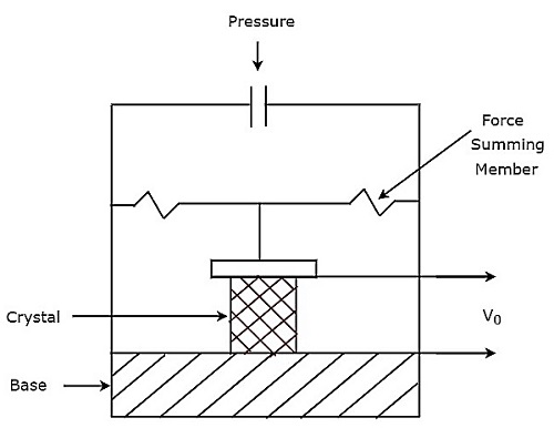
The output voltage, $V_{0}$ of above pressure transducer will be
$$V_{0}=\frac{Q}{C}$$
Photo Electric Transducer
An active transducer is said to be photo electric transducer, when it produces an electrical quantity which is equivalent to the illumination of light input. The circuit diagram of photo electric transducer is shown in below figure.
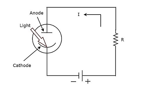
The working of photo electric transducer is mentioned below.
Step1 − The photo electric transducer releases electrons, when the light falls on cathode of it.
Step2 − The photo electric transducer produces a current, I in the circuit due to the attraction of electrons towards anode.
We can find the sensitivity of photo electric transducer by using the following formula.
$$S=\frac{I}{i}$$
Where,
$S$ is the sensitivity of photo electric transducer
$I$ is the output current of photo electric transducer
$i$ is the illumination of the light input of photo electric transducer
Thermo Electric Transducer
An active transducer is said to be thermo electric transducer, when it produces an electrical quantity which is equivalent to temperature input. The following two transducers are the examples of thermo electric transducers.
- Thermistor Transducer
- Thermocouple Transducer
Now, let us discuss about these two transducers one by one.
Thermistor Transducer
The resistor, which depends on temperature is called thermal resistor. In short, it is called Thermistor. The temperature coefficient of thermistor is negative. That means, as temperature increases, the resistance of thermistor decreases.
Mathematically, the relation between resistance of thermistor and temperature can be represented as
$$R_{1}=R_{2}e^\left ( \beta \left [ \frac{1}{T_{1}}-\frac{1}{T_{2}} \right ] \right )$$
Where,
$R_{1}$ is the resistance of thermistor at temperature ${T_{1}}^{0}K$
$R_{2}$ is the resistance of thermistor at temperature ${T_{2}}^{0}K$
$\beta$ is the temperature constant
The advantage of Thermistor transducer is that it will produce a fast and stable response.
Thermocouple Transducer
Thermocouple transducer produces an output voltage for a corresponding change of temperature at the input. If two wires of different metals are joined together in order to create two junctions, then that entire configuration is called Thermocouple. The circuit diagram of basic thermocouple is shown below −
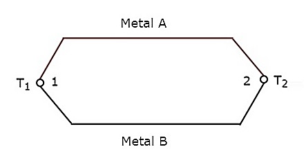
The above thermocouple has two metals, A & B and two junctions, 1 & 2. Consider a constant reference temperature, $T_{2}$ at junction 2. Let the temperature at junction, 1 is $T_{1}$. Thermocouple generates an emf (electro motive force), whenever the values of $T_{1}$ and $T_{2}$ are different.
That means, thermocouple generates an emf, whenever there is a temperature difference between the two junctions, 1 & 2 and it is directly proportional to the temperature difference between those two junctions. Mathematically, it can be represented as
$$e \alpha \left ( T_{1}-T_{2} \right )$$
Where,
$e$ is the emf generated by thermocouple
The above thermocouple circuit can be represented as shown in below figure for practical applications.
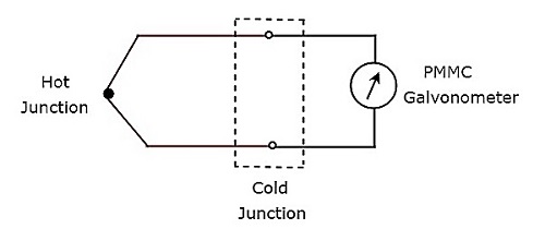
The part of the circuit, which lies between hot & cold junctions including those two junctions is an equivalent model of basic thermocouple. A PMMC galvanometer is connected across the cold junction and it deflects according to the emf generated across cold junction. Thermocouple transducer is the most commonly used thermoelectric transducer.
