- Home
- Introduction
- Performance Characteristics
- Measurement Errors
- Measuring Instruments
- DC Voltmeters
- AC Voltmeters
- Other AC Voltmeters
- DC Ammeters
- AC Ammeter
- OHMMeters
- MultiMeter
- Signal Generators
- Wave Analyzers
- Spectrum Analyzers
- Basics of Oscilloscopes
- Special Purpose Oscilloscopes
- Lissajous Figures
- CRO Probes
- Bridges
- DC Bridges
- AC Bridges
- Other AC Bridges
- Transducers
- Active Transducers
- Passive Transducers
- Measurement Of Displacement
- Data Acquisition Systems
Electronic Measuring Instruments - Bridges
If the electrical components are arranged in the form a bridge or ring structure, then that electrical circuit is called a bridge. In general, bridge forms a loop with a set of four arms or branches. Each branch may contain one or two electrical components.
Types of Bridges
We can classify the bridge circuits or bridges into the following two categories based on the voltage signal with which those can be operated.
- DC Bridges
- AC Bridges
Now, let us discuss about these two bridges briefly.
DC Bridges
If the bridge circuit can be operated with only DC voltage signal, then it is a DC bridge circuit or simply DC bridge. DC bridges are used to measure the value of unknown resistance. The circuit diagram of DC bridge looks like as shown in below figure.
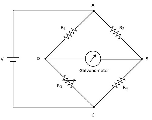
The above DC bridge has four arms and each arm consists of a resistor. Among which, two resistors have fixed resistance values, one resistor is a variable resistor and the other one has an unknown resistance value.
The above DC bridge circuit can be excited with a DC voltage source by placing it in one diagonal. The galvanometer is placed in other diagonal of DC bridge. It shows some deflection as long as the bridge is unbalanced.
Vary the resistance value of variable resistor until the galvanometer shows null (zero) deflection. Now, the above DC bridge is said to be a balanced one. So, we can find the value of unknown resistance by using nodal equations.
AC Bridges
If the bridge circuit can be operated with only AC voltage signal, then it is said to be AC bridge circuit or simply AC bridge. AC bridges are used to measure the value of unknown inductance, capacitance and frequency.
The circuit diagram of AC bridge looks like as shown in below figure.
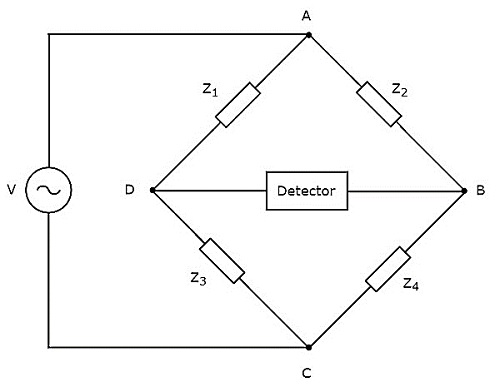
The circuit diagram of AC bridge is similar to that of DC bridge. The above AC bridge has four arms and each arm consists of some impedance. That means, each arm will be having either single or combination of passive elements such as resistor, inductor and capacitor.
Among the four impedances, two impedances have fixed values, one impedance is variable and the other one is an unknown impedance.
The above AC bridge circuit can be excited with an AC voltage source by placing it in one diagonal. A detector is placed in other diagonal of AC bridge. It shows some deflection as long as the bridge is unbalanced.
The above AC bridge circuit can be excited with an AC voltage source by placing it in one diagonal. A detector is placed in other diagonal of AC bridge. It shows some deflection as long as the bridge is unbalanced.
Vary the impedance value of variable impedance until the detector shows null (zero) deflection. Now, the above AC bridge is said to be a balanced one. So, we can find the value of unknown impedance by using balanced condition.
