- Home
- Introduction
- Performance Characteristics
- Measurement Errors
- Measuring Instruments
- DC Voltmeters
- AC Voltmeters
- Other AC Voltmeters
- DC Ammeters
- AC Ammeter
- OHMMeters
- MultiMeter
- Signal Generators
- Wave Analyzers
- Spectrum Analyzers
- Basics of Oscilloscopes
- Special Purpose Oscilloscopes
- Lissajous Figures
- CRO Probes
- Bridges
- DC Bridges
- AC Bridges
- Other AC Bridges
- Transducers
- Active Transducers
- Passive Transducers
- Measurement Of Displacement
- Data Acquisition Systems
Basics of Oscilloscopes
Oscilloscope is an electronic equipment, which displays a voltage waveform. Among the oscilloscopes, Cathode Ray Oscilloscope (CRO) is the basic one and it displays a time varying signal or waveform.
In this chapter, let us discuss about the block diagram of CRO and measurements of some parameters by using CRO.
Block Diagram of CRO
Cathode Ray Oscilloscope (CRO) consists a set of blocks. Those are vertical amplifier, delay line, trigger circuit, time base generator, horizontal amplifier, Cathode Ray Tube (CRT) & power supply. The block diagram of CRO is shown in below figure.
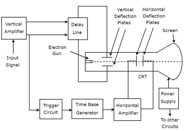
The function of each block of CRO is mentioned below.
Vertical Amplifier − It amplifies the input signal, which is to be displayed on the screen of CRT.
Delay Line − It provides some amount of delay to the signal, which is obtained at the output of vertical amplifier. This delayed signal is then applied to vertical deflection plates of CRT.
Trigger Circuit − It produces a triggering signal in order to synchronize both horizontal and vertical deflections of electron beam.
Time base Generator − It produces a sawtooth signal, which is useful for horizontal deflection of electron beam.
Horizontal Amplifier − It amplifies the sawtooth signal and then connects it to the horizontal deflection plates of CRT.
Power supply − It produces both high and low voltages. The negative high voltage and positive low voltage are applied to CRT and other circuits respectively.
Cathode Ray Tube (CRT) − It is the major important block of CRO and mainly consists of four parts. Those are electron gun, vertical deflection plates, horizontal deflection plates and fluorescent screen.
The electron beam, which is produced by an electron gun gets deflected in both vertical and horizontal directions by a pair of vertical deflection plates and a pair of horizontal deflection plates respectively. Finally, the deflected beam will appear as a spot on the fluorescent screen.
In this way, CRO will display the applied input signal on the screen of CRT. So, we can analyse the signals in time domain by using CRO
Measurements by using CRO
We can do the following measurements by using CRO.
- Measurement of Amplitude
- Measurement of Time Period
- Measurement of Frequency
Now, let us discuss about these measurements one by one.
Measurement of Amplitude
CRO displays the voltage signal as a function of time on its screen. The amplitude of that voltage signal is constant, but we can vary the number of divisions that cover the voltage signal in vertical direction by varying volt/division knob on the CRO panel. Therefore, we will get the amplitude of the signal, which is present on the screen of CRO by using following formula.
$$A=j\times n_{v}$$
Where,
$A$ is the amplitude
$j$ is the value of volt/division
$n_{v}$ is the number of divisions that cover the signal in vertical direction.
Measurement of Time Period
CRO displays the voltage signal as a function of time on its screen. The Time period of that periodic voltage signal is constant, but we can vary the number of divisions that cover one complete cycle of voltage signal in horizontal direction by varying time/division knob on the CRO panel.
Therefore, we will get the Time period of the signal, which is present on the screen of CRO by using following formula.
$$T=k\times n_{h}$$
Where,
$T$ is the Time period
$j$ is the value of time/division
$n_{v}$ is the number of divisions that cover one complete cycle of the periodic signal in horizontal direction.
Measurement of Frequency
The frequency, f of a periodic signal is the reciprocal of time period, T. Mathematically, it can be represented as
$$f=\frac{1}{T}$$
So, we can find the frequency, f of a periodic signal by following these two steps.
Step1 − Find the Time period of periodic signal
Step2 − Take reciprocal of Time period of periodic signal, which is obtained in Step1
We will discuss about special purpose oscilloscopes in next chapter.
