- Home
- Introduction
- Performance Characteristics
- Measurement Errors
- Measuring Instruments
- DC Voltmeters
- AC Voltmeters
- Other AC Voltmeters
- DC Ammeters
- AC Ammeter
- OHMMeters
- MultiMeter
- Signal Generators
- Wave Analyzers
- Spectrum Analyzers
- Basics of Oscilloscopes
- Special Purpose Oscilloscopes
- Lissajous Figures
- CRO Probes
- Bridges
- DC Bridges
- AC Bridges
- Other AC Bridges
- Transducers
- Active Transducers
- Passive Transducers
- Measurement Of Displacement
- Data Acquisition Systems
Special Purpose Oscilloscopes
In previous chapter, we had discussed about Cathode Ray Oscilloscope (CRO), which is a basic oscilloscope. We will get special purpose oscilloscopes just by including few additional blocks to the basic oscilloscope based on the requirement.
Following are the special purpose oscilloscopes.
- Dual Beam Oscilloscope
- Dual Trace Oscilloscope
- Digital Storage Oscilloscope
Now, let us discuss about these special purpose oscilloscopes one by one.
Dual Beam Oscilloscope
The Oscilloscope, which displays two voltage waveforms is called Dual Beam Oscilloscope. Its block diagram is shown in below figure.
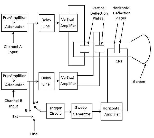
As shown in above figure, the CRT of Dual Beam Oscilloscope consists of two sets of vertical deflection plates and one set of horizontal deflection plates.
The combination of the following blocks together is called a channel.
- Pre-Amplifier & Attenuator
- Delay Line
- Vertical Amplifier
- A set of Vertical Deflection Plates
There are two channels in Dual Beam Oscilloscope. So, we can apply the two signals, namely A & B as input of channel A & Channel B respectively. We can choose any one of these four signals as trigger input to the trigger circuit by using a switch. Those are input signals A & B, External signal (Ext) and Line input.
This oscilloscope will produce two vertically deflected beams, since there are two pairs of vertical deflection plates. In this oscilloscope, the blocks which are useful for deflecting the beam in horizontal direction is common for both the input signals. Finally, this oscilloscope will produce the two input signals simultaneously on the screen of CRT.
Dual Trace Oscilloscope
The Oscilloscope, which produces two traces on its screen is called Dual Trace Oscilloscope. Its block diagram is shown in below figure.
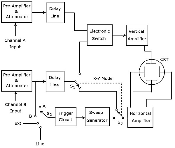
As shown in above figure, the CRT of Dual Trace Oscilloscope consists of a set of vertical deflection plates and another set of horizontal deflection plates. channel consists of four blocks, i.e. pre-Amplifier & attenuator, delay line, vertical amplifier and vertical deflection plates.
In above block diagram, the first two blocks are separately present in both channels. The last two blocks are common to both the channels. Hence, with the help of electronic switch we can connect the delay line output of a specific channel to vertical amplifier.
We can choose any one of these four signals as trigger input to the trigger circuit by using a switch. Those are input signals A & B, External signal (Ext) and Line input.
This oscilloscope uses same electron beam for deflecting the input signals A & B in vertical direction by using an electronic switch, and produces two traces. the blocks that deflect the beam horizontally is common for both the input signals.
Digital Storage Oscilloscope
The oscilloscope, which stores the waveform digitally is known as digital storage oscilloscope. The block diagram of (digital) storage oscilloscope is below −
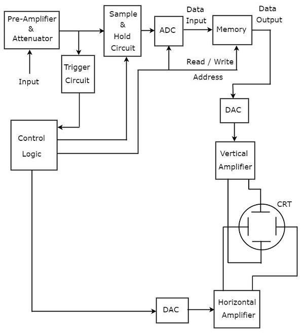
Additional blocks required for digital data storage are added to a basic oscilloscope to make it convert it into a Digital Storage Oscilloscope. The blocks that are required for storing of digital data are lies between the pre-amplifier & attenuator and vertical amplifier in Digital Storage Oscilloscope. Those are Sample and Hold circuit, Analog to Digital Converter (ADC), Memory & Digital to Analog Converter.
Control logic controls the first three blocks by sending various control signals. The blocks like control logic and Digital to Analog Converter are present between the trigger circuit and horizontal amplifier in Digital Storage Oscilloscope.
The Digital Storage Oscilloscope stores the data in digital before it displays the waveform on the screen. Whereas, the basic oscilloscope doesnt have this feature.
