- Home
- Introduction
- Performance Characteristics
- Measurement Errors
- Measuring Instruments
- DC Voltmeters
- AC Voltmeters
- Other AC Voltmeters
- DC Ammeters
- AC Ammeter
- OHMMeters
- MultiMeter
- Signal Generators
- Wave Analyzers
- Spectrum Analyzers
- Basics of Oscilloscopes
- Special Purpose Oscilloscopes
- Lissajous Figures
- CRO Probes
- Bridges
- DC Bridges
- AC Bridges
- Other AC Bridges
- Transducers
- Active Transducers
- Passive Transducers
- Measurement Of Displacement
- Data Acquisition Systems
AC Voltmeters
The instrument, which is used to measure the AC voltage across any two points of electric circuit is called AC voltmeter. If the AC voltmeter consists of rectifier, then it is said to be rectifier based AC voltmeter.
The DC voltmeter measures only DC voltages. If we want to use it for measuring AC voltages, then we have to follow these two steps.
Step1 − Convert the AC voltage signal into a DC voltage signal by using a rectifier.
Step2 − Measure the DC or average value of the rectifiers output signal.
We get Rectifier based AC voltmeter, just by including the rectifier circuit to the basic DC voltmeter. This chapter deals about rectifier based AC voltmeters.
Types of Rectifier based AC Voltmeters
Following are the two types of rectifier based AC voltmeters.
- AC voltmeter using Half Wave Rectifier
- AC voltmeter using Full Wave Rectifier
Now, let us discuss about these two AC voltmeters one by one.
AC Voltmeter using Half Wave Rectifier
If a Half wave rectifier is connected ahead of DC voltmeter, then that entire combination together is called AC voltmeter using Half wave rectifier. The block diagram of AC voltmeter using Half wave rectifier is shown in below figure.
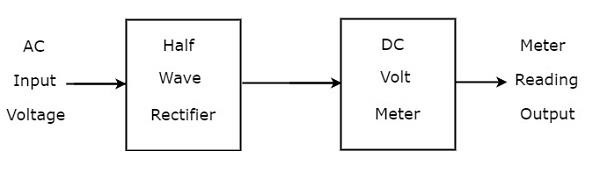
The above block diagram consists of two blocks: half wave rectifier and DC voltmeter. We will get the corresponding circuit diagram, just by replacing each block with the respective component(s) in above block diagram. So, the circuit diagram of AC voltmeter using Half wave rectifier will look like as shown in below figure.
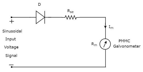
The rms value of sinusoidal (AC) input voltage signal is
$$V_{rms}=\frac{V_{m}}{\sqrt{2}}$$
$$\Rightarrow V_{m}=\sqrt{2} V_{rms}$$
$$\Rightarrow V_{m}=1.414 V_{rms}$$
Where,
$V_{m}$ is the maximum value of sinusoidal (AC) input voltage signal.
The DC or average value of the Half wave rectifiers output signal is
$$V_{dc}=\frac{V_{m}}{\pi}$$
Substitute, the value of $V_{m}$ in above equation.
$$V_{dc}= \frac{1.414 V_{rms}}{\pi}$$
$$V_{dc}= 0.45 V_{rms}$$
Therefore, the AC voltmeter produces an output voltage, which is equal to 0.45 times the rms value of the sinusoidal (AC) input voltage signal
AC Voltmeter using Full Wave Rectifier
If a Full wave rectifier is connected ahead of DC voltmeter, then that entire combination together is called AC voltmeter using Full wave rectifier. The block diagram of AC voltmeter using Full wave rectifier is shown in below figure
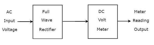
The above block diagram consists of two blocks: full wave rectifier and DC voltmeter. We will get the corresponding circuit diagram just by replacing each block with the respective component(s) in above block diagram.
So, the circuit diagram of AC voltmeter using Full wave rectifier will look like as shown in below figure.
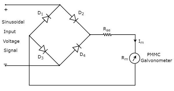
The rms value of sinusoidal (AC) input voltage signal is
$$V_{rms}=\frac{V_{m}}{\sqrt{2}}$$
$$\Rightarrow V_{m}=\sqrt{2} \:V_{rms}$$
$$\Rightarrow V_{m}= 1.414 V_{rms}$$
Where,
$V_{m}$ is the maximum value of sinusoidal (AC) input voltage signal.
The DC or average value of the Full wave rectifiers output signal is
$$V_{dc}=\frac{2V_{m}}{\pi}$$
Substitute, the value of $V_{m}$ in above equation
$$V_{dc}=\frac{2\times 1.414 \:V_{rms}}{\pi}$$
$$V_{dc}=0.9 \:V_{rms}$$
Therefore, the AC voltmeter produces an output voltage, which is equal to 0.9 times the rms value of the sinusoidal (AC) input voltage signal.
