- Home
- Introduction
- Performance Characteristics
- Measurement Errors
- Measuring Instruments
- DC Voltmeters
- AC Voltmeters
- Other AC Voltmeters
- DC Ammeters
- AC Ammeter
- OHMMeters
- MultiMeter
- Signal Generators
- Wave Analyzers
- Spectrum Analyzers
- Basics of Oscilloscopes
- Special Purpose Oscilloscopes
- Lissajous Figures
- CRO Probes
- Bridges
- DC Bridges
- AC Bridges
- Other AC Bridges
- Transducers
- Active Transducers
- Passive Transducers
- Measurement Of Displacement
- Data Acquisition Systems
AC Bridges
In this chapter, let us discuss about the AC bridges, which can be used to measure inductance. AC bridges operate with only AC voltage signal. The circuit diagram of AC bridge is shown in below figure.
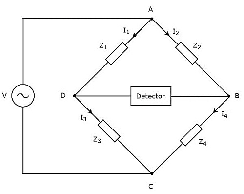
As shown in above figure, AC bridge mainly consists of four arms, which are connected in rhombus or square shape. All these arms consist of some impedance.
The detector and AC voltage source are also required in order to find the value of unknown impedance. Hence, one of these two are placed in one diagonal of AC bridge and the other one is placed in other diagonal of AC bridge. The balancing condition of Wheatstones bridge as −
$$R_{4}=\frac{R_{2}R_{3}}{R_{1}}$$
We will get the balancing condition of AC bridge, just by replacing R with Z in above equation.
$$Z_{4}=\frac{Z_{2}Z_{3}}{Z_{1}}$$
$\Rightarrow Z_{1}Z_{4}=Z_{2}Z_{3}$
Here, $Z_{1}$ and $Z_{2}$ are fixed impedances. Whereas, $Z_{3}$ is a standard variable impedance and $Z_{4}$ is an unknown impedance.
Note − We can choose any two of those four impedances as fixed impedances, one impedance as standard variable impedance & the other impedance as an unknown impedance based on the application.
Following are the two AC bridges, which can be used to measure inductance.
- Maxwells Bridge
- Hays Bridge
Now, let us discuss about these two AC bridges one by one.
Maxwell's Bridge
Maxwells bridge is an AC bridge having four arms, which are connected in the form of a rhombus or square shape. Two arms of this bridge consist of a single resistor, one arm consists of a series combination of resistor and inductor & the other arm consists of a parallel combination of resistor and capacitor.
An AC detector and AC voltage source are used to find the value of unknown impedance. Hence, one of these two are placed in one diagonal of Maxwells bridge and the other one is placed in other diagonal of Maxwells bridge.
Maxwells bridge is used to measure the value of medium inductance. The circuit diagram of Maxwells bridge is shown in the below figure.
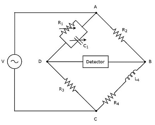
In above circuit, the arms AB, BC, CD and DA together form a rhombus or square shape. The arms AB and CD consist of resistors, $R_{2}$ and $R_{3}$ respectively. The arm, BC consists of a series combination of resistor, $R_{4}$ and inductor, $L_{4}$. The arm, DA consists of a parallel combination of resistor, $R_{1}$ and capacitor, $C_{1}$.
Let, $Z_{1}, Z_{2}, Z_{3}$ and $Z_{4}$ are the impedances of arms DA, AB, CD and BC respectively. The values of these impedances will be
$$Z_{1}=\frac{R_{1}\left ( \frac{1}{j\omega C_{1}} \right )}{R_{1}+\frac{1}{j\omega C_{1}}}$$
$$\Rightarrow Z_{1}=\frac{R_{1}}{1+j \omega R_{1}C_{1}}$$
$Z_{2}=R_{2}$
$Z_{3}=R_{3}$
$Z_{4}=R_{4}+j \omega L_{4}$
Substitute these impedance values in the following balancing condition of AC bridge.
$$Z_{4}=\frac{Z_{2}Z_{3}}{Z_{1}}$$
$$R_{4}+j\omega L_{4}=\frac{R_{2}R_{3}}{\left ( {\frac{R_{1}}{1+j \omega R_{1}C_{1}}} \right )}$$
$\Rightarrow R_{4}+j\omega L_{4}=\frac{R_{2}R_{3}\left (1+j \omega R_{1}C_{1} \right )}{R_{1}}$
$\Rightarrow R_{4}+j\omega L_{4}=\frac{R_{2}R_{3}}{R_{1}}+\frac{j \omega R_{1}C_{1}R_{2}R_{3}}{R_{1}}$
$\Rightarrow R_{4}+j\omega L_{4}=\frac{R_{2}R_{3}}{R_{1}}+j \omega C_{1}R_{2}R_{3}$
By comparing the respective real and imaginary terms of above equation, we will get
$R_{4}=\frac{R_{2}R_{3}}{R_{1}}$Equation 1
$L_{4}=C_{1}R_{2}R_{3}$Equation 2
By substituting the values of resistors $R_{1}$, $R_{2}$ and $R_{3}$ in Equation 1, we will get the value of resistor, $R_{4}$. Similarly, by substituting the value of capacitor, $C_{1}$ and the values of resistors, $R_{2}$ and $R_{3}$ in Equation 2, we will get the value of inductor, $L_{4}$.
The advantage of Maxwells bridge is that both the values of resistor, $R_{4}$ and an inductor, $L_{4}$ are independent of the value of frequency.
Hays Bridge
Hays bridge is a modified version of Maxwells bridge, which we get by modifying the arm, which consists of a parallel combination of resistor and capacitor into the arm, which consists of a series combination of resistor and capacitor in Maxwells bridge.
Hays bridge is used to measure the value of high inductance. The circuit diagram of Hays bridge is shown in the below figure.
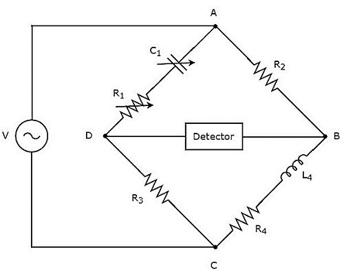
In above circuit, the arms AB, BC, CD and DA together form a rhombus or square shape. The arms, AB and CD consist of resistors, $R_{2}$ and $R_{3}$ respectively. The arm, BC consists of a series combination of resistor, $R_{4}$ and inductor, $L_{4}$. The arm, DA consists of a series combination of resistor, $R_{1}$ and capacitor, $C_{1}$.
Let, $Z_{1}, Z_{2}, Z_{3}$ and $Z_{4}$ are the impedances of arms DA, AB, CD and BC respectively. The values of these impedances will be
$$Z_{1}=R_{1}+\frac{1}{j \omega C_{1}}$$
$\Rightarrow Z_{1}=\frac{1+j \omega R_{1}C_{1}}{j \omega C_{1}}$
$Z_{2}=R_{2}$
$Z_{3}=R_{3}$
$Z_{4}=R_{4}+j \omega L_{4}$
Substitute these impedance values in the following balancing condition of AC bridge.
$$Z_{4}=\frac{Z_{2}Z_{3}}{Z_{1}}$$
$R_{4}+j \omega L_{4}=\frac{R_{2}R_{3}}{\left ( \frac{1+j \omega R_{1}C_{1}}{j \omega C_{1}}\right )}$
$R_{4}+j \omega L_{4}=\frac{R_{2}R_{3}j \omega C_{1}}{\left ( 1+j \omega R_{1}C_{1}\right )}$
Multiply the numerator and denominator of right hand side term of above equation with $1 - j \omega R_{1}C_{1}$.
$\Rightarrow R_{4}+j \omega L_{4}=\frac{R_{2}R_{3}j \omega C_{1}}{\left ( 1+j \omega R_{1}C_{1}\right )}\times \frac{\left (1 - j \omega R_{1}C_{1} \right )}{\left (1 - j \omega R_{1}C_{1} \right )}$
$\Rightarrow R_{4}+j \omega L_{4}=\frac{\omega^{2}{C_{1}}^{2}R_{1}R_{2}R_{3}+j \omega R_{2}R_{3}C_{1}}{\left ( 1+\omega^{2}{R_{1}}^{2}{C_{1}}^{2}\right )}$
By comparing the respective real and imaginary terms of above equation, we will get
$R_{4}= \frac{\omega^{2}{C_{1}}^{2}R_{1}R_{2}R_{3}}{\left ( 1+\omega^{2}{R_{1}}^{2}{C_{1}}^{2}\right )}$Equation 3
$L_{4}= \frac{R_{2}R_{3}C_{1}}{\left ( 1+\omega^{2}{R_{1}}^{2}{C_{1}}^{2}\right )}$Equation 4
By substituting the values of $R_{1}, R_{2}, R_{3}, C_{1}$ and $\omega$ in Equation 3 and Equation 4, we will get the values of resistor, $R_{4}$ and inductor, $L_{4}$.
