- Home
- Introduction
- Performance Characteristics
- Measurement Errors
- Measuring Instruments
- DC Voltmeters
- AC Voltmeters
- Other AC Voltmeters
- DC Ammeters
- AC Ammeter
- OHMMeters
- MultiMeter
- Signal Generators
- Wave Analyzers
- Spectrum Analyzers
- Basics of Oscilloscopes
- Special Purpose Oscilloscopes
- Lissajous Figures
- CRO Probes
- Bridges
- DC Bridges
- AC Bridges
- Other AC Bridges
- Transducers
- Active Transducers
- Passive Transducers
- Measurement Of Displacement
- Data Acquisition Systems
Signal Generators
Signal generator is an electronic equipment that provides standard test signals like sine wave, square wave, triangular wave and etc. It is also called an oscillator, since it produces periodic signals.
The signal generator, which produces the periodic signal having a frequency of Audio Frequency (AF) range is called AF signal generator. the range of audio frequencies is 20Hz to 20KHz.
AF Sine and Square Wave Generator
The AF signal generator, which generates either sine wave or square wave in the range of audio frequencies based on the requirement is called AF Sine and Square wave generator. Its block diagramis shown in below figure.
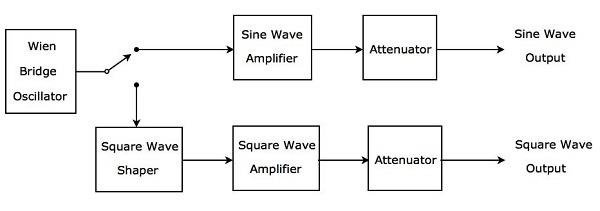
The above block diagram consists of mainly two paths. Those are upper path and lower path. Upper path is used to produce AF sine wave and the lower path is used to produce AF square wave.
Wien bridge oscillator will produce a sine wave in the range of audio frequencies. Based on the requirement, we can connect the output of Wien bridge oscillator to either upper path or lower path by a switch.
The upper path consists of the blocks like sine wave amplifier and attenuator. If the switch is used to connect the output of Wien bridge oscillator to upper path, it will produce a desired AF sine wave at the output of upper path.
The lower path consists of the following blocks: square wave shaper, square wave amplifier, and attenuator. The square wave shaper converts the sine wave into a square wave. If the switch is used to connect the output of Wien bridge oscillator to lower path, then it will produce a desired AF square wave at the output of lower path. In this way, the block diagram that we considered can be used to produce either AF sine wave or AF square wave based on the requirement.
Function Generator
Function generator is a signal generator, which generates three or more periodic waves. Consider the following block diagram of a Function generator, which will produce periodic waves like triangular wave, square wave and sine wave.
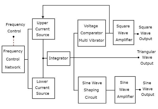
There are two current sources, namely upper current source and lower current source in above block diagram. These two current sources are regulated by the frequency-controlled voltage.
Triangular Wave
Integrator present in the above block diagram, gets constant current alternately from upper and lower current sources for equal amount of time repeatedly. So, the integrator will produce two types of output for the same time repeatedly −
The output voltage of an integrator increases linearly with respect to time for the period during which integrator gets current from upper current source.
The output voltage of an integrator decreases linearly with respect to time for the period during which integrator gets current from lower current source.
In this way, the integrator present in above block diagram will produce a triangular wave.
Square Wave & Sine Wave
The output of integrator, i.e. the triangular wave is applied as an input to two other blocks as shown in above block diagram in order to get the square wave and sine wave respectively. Let us discuss about these two one by one.
Square Wave
The triangular wave has positive slope and negative slope alternately for equal amount of time repeatedly. So, the voltage comparator multi vibrator present in above block diagram will produce the following two types of output for equal amount of time repeatedly.
One type of constant (higher) voltage at the output of voltage comparator multi vibrator for the period during which the voltage comparator multi vibrator gets the positive slope of the triangular wave.
Another type of constant (lower) voltage at the output of voltage comparator multi vibrator for the period during which the voltage comparator multi vibrator gets the negative slope of the triangular wave.
The voltage comparator multi vibrator present in above block diagram will produce a square wave. If the amplitude of the square wave that is produced at the output of voltage comparator multi vibrator is not sufficient, then it can be amplified to the required value by using a square wave amplifier.
Sine Wave
The sine wave shaping circuit will produce a sine wave output from the triangular input wave. Basically, this circuit consists of a diode resistance network. If the amplitude of the sine wave produced at the output of sine wave shaping circuit is insufficient, then it can be amplified to the required value by using sine wave amplifier.
