- Home
- Introduction
- Performance Characteristics
- Measurement Errors
- Measuring Instruments
- DC Voltmeters
- AC Voltmeters
- Other AC Voltmeters
- DC Ammeters
- AC Ammeter
- OHMMeters
- MultiMeter
- Signal Generators
- Wave Analyzers
- Spectrum Analyzers
- Basics of Oscilloscopes
- Special Purpose Oscilloscopes
- Lissajous Figures
- CRO Probes
- Bridges
- DC Bridges
- AC Bridges
- Other AC Bridges
- Transducers
- Active Transducers
- Passive Transducers
- Measurement Of Displacement
- Data Acquisition Systems
DC Voltmeters
DC voltmeter is a measuring instrument, which is used to measure the DC voltage across any two points of electric circuit. If we place a resistor in series with the Permanent Magnet Moving Coil (PMMC) galvanometer, then the entire combination together acts as DC voltmeter.
The series resistance, which is used in DC voltmeter is also called series multiplier resistance or simply, multiplier. It basically limits the amount of current that flows through galvanometer in order to prevent the meter current from exceeding the full scale deflection value. The circuit diagram of DC voltmeter is shown in below figure.
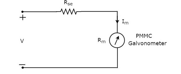
We have to place this DC voltmeter across the two points of an electric circuit, where the DC voltage is to be measured.
Apply KVL around the loop of above circuit.
$V-I_{m}R_{se}-I_{m}R_{m}=0$ (Equation 1)
$$\Rightarrow V-I_{m}R_{m}=I_{m}R_{se}$$
$$\Rightarrow R_{se}=\frac{V-I_{m}R_{m}}{I_{m}}$$
$\Rightarrow R_{se}=\frac{V}{I_{m}}-R_{m}$ (Equation 2)
Where,
$R_{se}$ is the series multiplier resistance
$V$ is the full range DC voltage that is to be measured
$I_{m}$ is the full scale deflection current
$R_{m}$ is the internal resistance of galvanometer
The ratio of full range DC voltage that is to be measured, $V$ and the DC voltage drop across the galvanometer, $V_{m}$ is known as multiplying factor, m. Mathematically, it can be represented as
$m=\frac{V}{V_{m}}$ (Equation 3)
From Equation 1, we will get the following equation for full range DC voltage that is to be measured, $V$.
$V=I_{m}R_{se}+I_{m}R_{m}$ (Equation 4)
The DC voltage drop across the galvanometer, $V_{m}$ is the product of full scale deflection current, $I_{m}$ and internal resistance of galvanometer, $R_{m}$. Mathematically, it can be written as
$V_{m}=I_{m}R_{m}$ (Equation 5)
Substitute, Equation 4 and Equation 5 in Equation 3.
$$m=\frac{I_{m}R_{se}+I_{m}R_{m}}{I_{m}R_{m}}$$
$\Rightarrow m=\frac{R_{se}}{R_{m}}+1$
$\Rightarrow m-1=\frac{R_{se}}{R_{m}}$
$R_{se}=R_{m}\left (m-1 \right )$(Equation 6)
We can find the value of series multiplier resistance by using either Equation 2 or Equation 6 based on the available data.
Multi Range DC Voltmeter
In previous section, we had discussed DC voltmeter, which is obtained by placing a multiplier resistor in series with the PMMC galvanometer. This DC voltmeter can be used to measure a particular range of DC voltages.
If we want to use the DC voltmeter for measuring the DC voltages of multiple ranges, then we have to use multiple parallel multiplier resistors instead of single multiplier resistor and this entire combination of resistors is in series with the PMMC galvanometer. The circuit diagram of multi range DC voltmeter is shown in below figure.
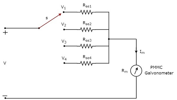
We have to place this multi range DC voltmeter across the two points of an electric circuit, where the DC voltage of required range is to be measured. We can choose the desired range of voltages by connecting the switch s to the respective multiplier resistor.
Let, $m_{1},m_{2}, m_{2} $ and $m_{4}$ are the multiplying factors of DC voltmeter when we consider the full range DC voltages to be measured as, $V_{1} , V_{2}, V_{3}$ and $V_{4}$ respectively. Following are the formulae corresponding to each multiplying factor.
$$m_{1}=\frac{V_{1}}{V_{m}}$$
$$m_{2}=\frac{V_{2}}{V_{m}}$$
$$m_{3}=\frac{V_{3}}{V_{m}}$$
$$m_{4}=\frac{V_{4}}{V_{m}}$$
In above circuit, there are four series multiplier resistors, $R_{se1}, R_{se2}, R_{se3}$ and $R_{se4}$. Following are the formulae corresponding to these four resistors.
$$R_{se1}=R_{m}\left (m_{1}-1 \right )$$
$$R_{se2}=R_{m}\left (m_{2}-1 \right )$$
$$R_{se3}=R_{m}\left (m_{3}-1 \right )$$
$$R_{se4}=R_{m}\left (m_{4}-1 \right )$$
So, we can find the resistance values of each series multiplier resistor by using above formulae.
