- Home
- Introduction
- Performance Characteristics
- Measurement Errors
- Measuring Instruments
- DC Voltmeters
- AC Voltmeters
- Other AC Voltmeters
- DC Ammeters
- AC Ammeter
- OHMMeters
- MultiMeter
- Signal Generators
- Wave Analyzers
- Spectrum Analyzers
- Basics of Oscilloscopes
- Special Purpose Oscilloscopes
- Lissajous Figures
- CRO Probes
- Bridges
- DC Bridges
- AC Bridges
- Other AC Bridges
- Transducers
- Active Transducers
- Passive Transducers
- Measurement Of Displacement
- Data Acquisition Systems
Wave Analyzers
The electronic instrument used to analyze waves is called wave analyzer. It is also called signal analyzer, since the terms signal and wave can be interchangeably used frequently.
We can represent the periodic signal as sum of the following two terms.
- DC component
- Series of sinusoidal harmonics
So, analyzation of a periodic signal is analyzation of the harmonics components presents in it.
Basic Wave Analyzer
Basic wave analyzer mainly consists of three blocks − the primary detector, full wave rectifier, and PMMC galvanometer. The block diagram of basic wave analyzer is shown in below figure −
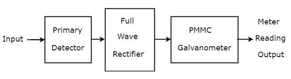
The function of each block present in basic wave analyzer is mentioned below.
Primary Detector − It consists of an LC circuit. We can adjust the values of inductor, L and capacitor, C in such a way that it allows only the desired harmonic frequency component that is to be measured.
Full Wave Rectifier − It converts the AC input into a DC output.
PMMC Galvanometer − It shows the peak value of the signal, which is obtained at the output of Full wave rectifier.
We will get the corresponding circuit diagram, just by replacing each block with the respective component(s) in above block diagram of basic wave analyzer. So, the circuit diagram of basic wave analyzer will look like as shown in the following figure −
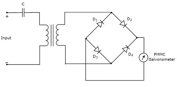
This basic wave analyzer can be used for analyzing each and every harmonic frequency component of a periodic signal.
Types of Wave Analyzers
Wave analyzers can be classified into the following two types.
- Frequency Selective Wave Analyzer
- Superheterodyne Wave Analyzer
Now, let us discuss about these two wave analyzers one by one.
Frequency Selective Wave Analyzer
The wave analyzer, used for analyzing the signals are of AF range is called frequency selective wave analyzer. The block diagram of frequency selective wave analyzer is shown in below figure.
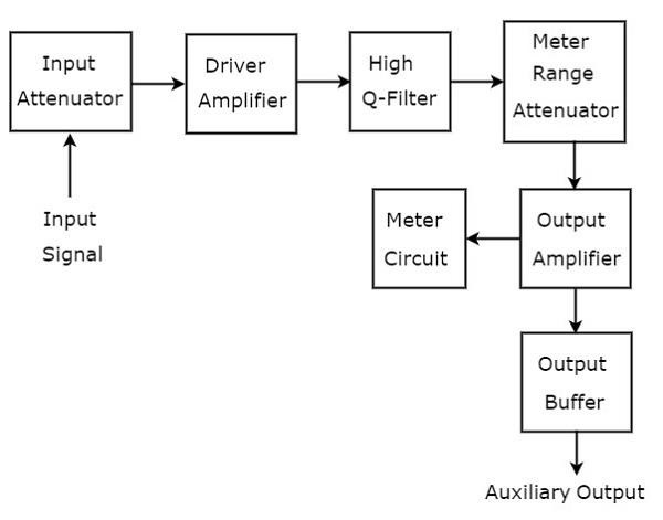
Frequency selective wave analyzer consists a set of blocks. The function of each block is mentioned below.
Input Attenuator − The AF signal, which is to be analyzed is applied to input attenuator. If the signal amplitude is too large, then it can be attenuated by input attenuator.
Driver Amplifier − It amplifies the received signal whenever necessary.
High Q-filter − It is used to select the desired frequency and reject unwanted frequencies. It consists of two RC sections and two filter amplifiers & all these are cascaded with each other. We can vary the capacitance values for changing the range of frequencies in powers of 10. Similarly, we can vary the resistance values in order to change the frequency within a selected range.
Meter Range Attenuator − It gets the selected AF signal as an input & produces an attenuated output, whenever required.
Output Amplifier − It amplifies the selected AF signal if necessary.
Output Buffer − It is used to provide the selected AF signal to output devices.
Meter Circuit − It displays the reading of selected AF signal. We can choose the meter reading in volt range or decibel range.
Superheterodyne Wave Analyzer
The wave analyzer, used to analyze the signals of RF range is called superheterodyne wave analyzer. The following figure shows the block diagram of superheterodyne wave analyzer.
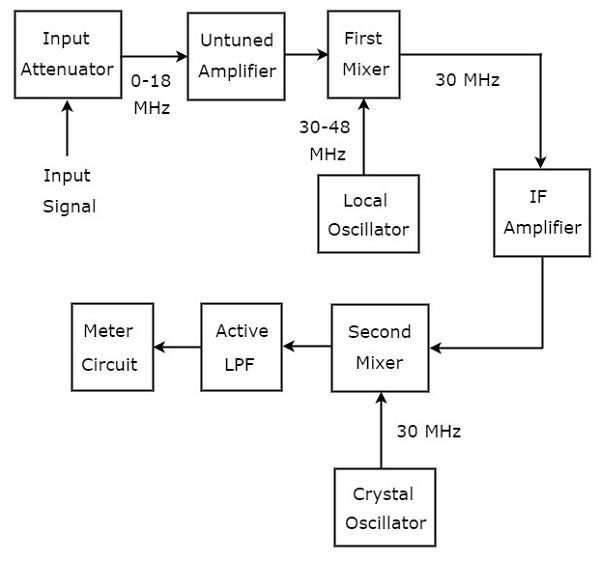
The working of superheterodyne wave analyzer is mentioned below.
The RF signal, which is to be analyzed is applied to the input attenuator. If the signal amplitude is too large, then it can be attenuated by input attenuator.
Untuned amplifier amplifies the RF signal whenever necessary and it is applied to first mixer.
The frequency ranges of RF signal & output of Local oscillator are 0-18 MHz & 30-48 MHz respectively. So, first mixer produces an output, which has frequency of 30 MHz. This is the difference of frequencies of the two signals that are applied to it.
IF amplifier amplifies the Intermediate Frequency (IF) signal, i.e. the output of first mixer. The amplified IF signal is applied to second mixer.
The frequencies of amplified IF signal & output of Crystal oscillator are same and equal to 30MHz. So, the second mixer produces an output, which has frequency of 0 Hz. This is the difference of frequencies of the two signals that are applied to it.
The cut off frequency of Active Low Pass Filter (LPF) is chosen as 1500 Hz. Hence, this filter allows the output signal of second mixer.
Meter Circuit displays the reading of RF signal. We can choose the meter reading in volt range or decibel range.
So, we can choose a particular wave analyzer based on the frequency range of the signal that is to be analyzed.