- Linear Integrated Circuits Applications
- Home
- Basics of Integrated Circuits Applications
- Basics Operational Amplifier
- Op-Amp applications
- Arithmetic Circuits
- Differentiator & Integrator
- Converters Of Electrical Quantities
- Comparators
- Log & Anti-Log Amplifiers
- Rectifiers
- Clippers
- Clampers
- Active Filters
- Sinusoidal Oscillators
- Waveform Generators
- 555 Timer
- Phase Locked Loop Ic
- Voltage Regulators
- Data Converters
- Digital to Analog Converters
- DAC Example Problem
- Direct Type ADCs
- Indirect Type ADC
- Useful Resources
- Quick Guide
- Useful Resources
- Discussion
Sinusoidal Oscillators
An oscillator is an electronic circuit that produces a periodic signal. If the oscillator produces sinusoidal oscillations, it is called as a sinusoidal oscillator. It converts the input energy from a DC source into an AC output energy of a periodic signal. This periodic signal will be having a specific frequency and amplitude.
The block diagram of a sinusoidal oscillator is shown in the following figure −
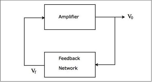
The above figure mainly consists of two blocks: an amplifier and a feedback network.The feedback network takes a part of the output of amplifier as an input to it and produces a voltage signal. This voltage signal is applied as an input to the amplifier.
The block diagram of a sinusoidal oscillator shown above produces sinusoidal oscillations, when the following two conditions are satisfied −
The loop gain $A_{v}\beta$ of the above block diagram of sinusoidal oscillator must be greater than or equal to unity. Here, $A_{v}$ and $\beta$ are the gain of amplifier and gain of the feedback network, respectively.
The total phase shift around the loop of the above block diagram of a sinusoidal oscillator must be either 00 or 3600.
The above two conditions together are called as Barkhausen criteria.
Op-Amp Based Oscillators
There are two types of op-amp based oscillators.
- RC phase shift oscillator
- Wien bridge oscillator
This section discusses each of them in detail.
RC Phase Shift Oscillator
The op-amp based oscillator, which produces a sinusoidal voltage signal at the output with the help of an inverting amplifier and a feedback network is known as a RC phase shift oscillator. This feedback network consists of three cascaded RC sections.
The circuit diagram of a RC phase shift oscillator is shown in the following figure −
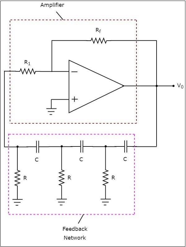
In the above circuit, the op-amp is operating in inverting mode. Hence, it provides a phase shift of 1800. The feedback network present in the above circuit also provides a phase shift of 1800, since each RC section provides a phase shift of 600. Therefore, the above circuit provides a total phase shift of 3600 at some frequency.
The output frequency of a RC phase shift oscillator is −
$$f=\frac{1}{2\Pi RC\sqrt[]{6}}$$
The gain $A_{v}$ of an inverting amplifier should be greater than or equal to -29,
$$i.e.,-\frac{R_f}{R_1}\geq-29$$
$$=>\frac{R_f}{R_1}\geq-29$$
$$=>R_{f}\geq29R_{1}$$
So, we should consider the value of feedback resistor $R_{f}$, as minimum of 29 times the value of resistor $R_{1}$, in order to produce sustained oscillations at the output of a RC phase shift oscillator.
Wien Bridge Oscillator
The op-amp based oscillator, which produces a sinusoidal voltage signal at the output with the help of a non-inverting amplifier and a feedback network is known as Wien bridge oscillator.
The circuit diagram of a Wien bridge oscillator is shown in the following figure −
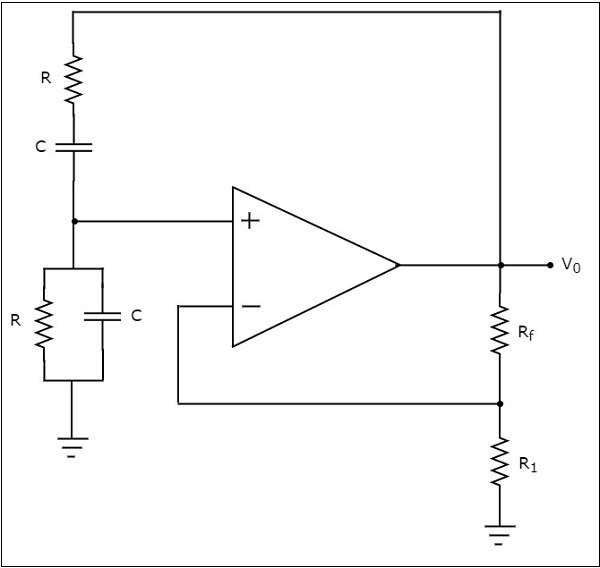
In the circuit shown above for Wein bridge oscillator, the op-amp is operating in non inverting mode. Hence, it provides a phase shift of 00. So, the feedback network present in the above circuit should not provide any phase shift.
If the feedback network provides some phase shift, then we have to balance the bridge in such a way that there should not be any phase shift. So, the above circuit provides a total phase shift of 00 at some frequency.
The output frequency of Wien bridge oscillator is
$$f=\frac{1}{2\Pi RC}$$
The gain $A_{v}$ of the non-inverting amplifier should be greater than or equal to 3
$$i.e.,1+\frac{R_f}{R_1}\geq3$$
$$=>\frac{R_f}{R_1}\geq2$$
$$=>R_{f}\geq2R_{1}$$
So, we should consider the value of feedback resistor $R_{f}$ at least twice the value of resistor, $R_{1}$ in order to produce sustained oscillations at the output of Wien bridge oscillator.