- Linear Integrated Circuits Applications
- Home
- Basics of Integrated Circuits Applications
- Basics Operational Amplifier
- Op-Amp applications
- Arithmetic Circuits
- Differentiator & Integrator
- Converters Of Electrical Quantities
- Comparators
- Log & Anti-Log Amplifiers
- Rectifiers
- Clippers
- Clampers
- Active Filters
- Sinusoidal Oscillators
- Waveform Generators
- 555 Timer
- Phase Locked Loop Ic
- Voltage Regulators
- Data Converters
- Digital to Analog Converters
- DAC Example Problem
- Direct Type ADCs
- Indirect Type ADC
- Useful Resources
- Quick Guide
- Useful Resources
- Discussion
Log And Anti Log Amplifiers
The electronic circuits which perform the mathematical operations such as logarithm and anti-logarithm (exponential) with an amplification are called as Logarithmic amplifier and Anti-Logarithmic amplifier respectively.
This chapter discusses about the Logarithmic amplifier and Anti-Logarithmic amplifier in detail. Please note that these amplifiers fall under non-linear applications.
Logarithmic Amplifier
A logarithmic amplifier, or a log amplifier, is an electronic circuit that produces an output that is proportional to the logarithm of the applied input. This section discusses about the op-amp based logarithmic amplifier in detail.
An op-amp based logarithmic amplifier produces a voltage at the output, which is proportional to the logarithm of the voltage applied to the resistor connected to its inverting terminal. The circuit diagram of an op-amp based logarithmic amplifier is shown in the following figure −
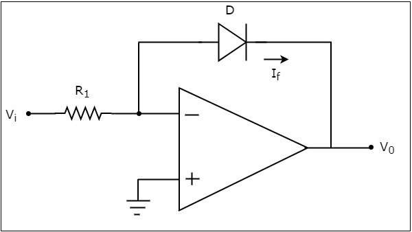
In the above circuit, the non-inverting input terminal of the op-amp is connected to ground. That means zero volts is applied at the non-inverting input terminal of the op-amp.
According to the virtual short concept, the voltage at the inverting input terminal of an op-amp will be equal to the voltage at its non-inverting input terminal. So, the voltage at the inverting input terminal will be zero volts.
The nodal equation at the inverting input terminal’s node is −
$$\frac{0-V_i}{R_1}+I_{f}=0$$
$$=>I_{f}=\frac{V_i}{R_1}......Equation 1$$
The following is the equation for current flowing through a diode, when it is in forward bias −
$$I_{f}=I_{s} e^{(\frac{V_f}{nV_T})} ......Equation 2$$
where,
$I_{s}$ is the saturation current of the diode,
$V_{f}$ is the voltage drop across diode, when it is in forward bias,
$V_{T}$ is the diode’s thermal equivalent voltage.
The KVL equation around the feedback loop of the op amp will be −
$$0-V_{f}-V_{0}=0$$
$$=>V_{f}=-V_{0}$$
Substituting the value of $V_{f}$ in Equation 2, we get −
$$I_{f}=I_{s} e^{\left(\frac{-V_0}{nV_T}\right)} ......Equation 3$$
Observe that the left hand side terms of both equation 1 and equation 3 are same. Hence, equate the right hand side term of those two equations as shown below −
$$\frac{V_i}{R_1}=I_{s}e^{\left(\frac{-V_0}{nV_T}\right)}$$
$$\frac{V_i}{R_1I_s}= e^{\left(\frac{-V_0}{nV_T}\right)}$$
Applying natural logarithm on both sides, we get −
$$In\left(\frac{V_i}{R_1I_s}\right)= \frac{-V_0}{nV_T}$$
$$V_{0}=-{nV_T}In\left(\frac{V_i}{R_1I_s}\right)$$
Note that in the above equation, the parameters n, ${V_T}$ and $I_{s}$ are constants. So, the output voltage $V_{0}$ will be proportional to the natural logarithm of the input voltage $V_{i}$ for a fixed value of resistance $R_{1}$.
Therefore, the op-amp based logarithmic amplifier circuit discussed above will produce an output, which is proportional to the natural logarithm of the input voltage ${V_T}$, when ${R_1I_s}=1V$.
Observe that the output voltage $V_{0}$ has a negative sign, which indicates that there exists a 1800 phase difference between the input and the output.
Anti-Logarithmic Amplifier
An anti-logarithmic amplifier, or an anti-log amplifier, is an electronic circuit that produces an output that is proportional to the anti-logarithm of the applied input. This section discusses about the op-amp based anti-logarithmic amplifier in detail.
An op-amp based anti-logarithmic amplifier produces a voltage at the output, which is proportional to the anti-logarithm of the voltage that is applied to the diode connected to its inverting terminal.
The circuit diagram of an op-amp based anti-logarithmic amplifier is shown in the following figure −
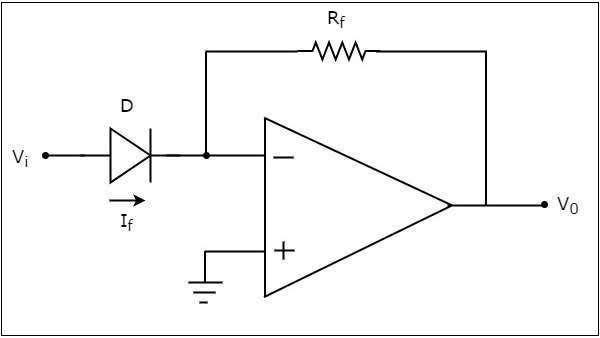
In the circuit shown above, the non-inverting input terminal of the op-amp is connected to ground. It means zero volts is applied to its non-inverting input terminal.
According to the virtual short concept, the voltage at the inverting input terminal of op-amp will be equal to the voltage present at its non-inverting input terminal. So, the voltage at its inverting input terminal will be zero volts.
The nodal equation at the inverting input terminal’s node is −
$$-I_{f}+\frac{0-V_0}{R_f}=0$$
$$=>-\frac{V_0}{R_f}=I_{f}$$
$$=>V_{0}=-R_{f}I_{f}.........Equation 4$$
We know that the equation for the current flowing through a diode, when it is in forward bias, is as given below −
$$I_{f}=I_{s} e^{\left(\frac{V_f}{nV_T}\right)}$$
Substituting the value of $I_{f}$ in Equation 4, we get
$$V_{0}=-R_{f}\left \{{I_{s} e^{\left(\frac{V_f}{nV_T}\right)}}\right \}$$
$$V_{0}=-R_{f}{I_{s} e^{\left(\frac{V_f}{nV_T}\right)}}......Equation 5$$
The KVL equation at the input side of the inverting terminal of the op amp will be
$$V_{i}-V_{f}=0$$
$$V_{f}=V_{i}$$
Substituting, the value of 𝑉𝑓 in the Equation 5, we get −
$$V_{0}=-R_{f}{I_{s} e^{\left(\frac{V_i}{nV_T}\right)}}$$
Note that, in the above equation the parameters n, ${V_T}$ and $I_{s}$ are constants. So, the output voltage ${V_0}$ will be proportional to the anti-natural logarithm (exponential) of the input voltage ${V_i}$, for a fixed value of feedback resistance ${R_f}$.
Therefore, the op-amp based anti-logarithmic amplifier circuit discussed above will produce an output, which is proportional to the anti-natural logarithm (exponential) of the input voltage ${V_i}$ when, ${R_fI_s}= 1V$. Observe that the output voltage ${V_0}$ is having a negative sign, which indicates that there exists a 1800 phase difference between the input and the output.