- Linear Integrated Circuits Applications
- Home
- Basics of Integrated Circuits Applications
- Basics Operational Amplifier
- Op-Amp applications
- Arithmetic Circuits
- Differentiator & Integrator
- Converters Of Electrical Quantities
- Comparators
- Log & Anti-Log Amplifiers
- Rectifiers
- Clippers
- Clampers
- Active Filters
- Sinusoidal Oscillators
- Waveform Generators
- 555 Timer
- Phase Locked Loop Ic
- Voltage Regulators
- Data Converters
- Digital to Analog Converters
- DAC Example Problem
- Direct Type ADCs
- Indirect Type ADC
- Useful Resources
- Quick Guide
- Useful Resources
- Discussion
Comparators
A comparator is an electronic circuit, which compares the two inputs that are applied to it and produces an output. The output value of the comparator indicates which of the inputs is greater or lesser. Please note that comparator falls under non-linear applications of ICs.
An op-amp consists of two input terminals and hence an op-amp based comparator compares the two inputs that are applied to it and produces the result of comparison as the output. This chapter discusses about op-amp based comparators.
Types of Comparators
Comparators are of two types : Inverting and Non-inverting. This section discusses about these two types in detail.
Inverting Comparator
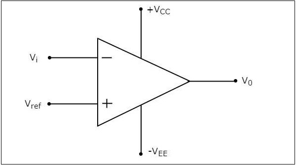
An inverting comparator is an op-amp based comparator for which a reference voltage is applied to its non-inverting terminal and the input voltage is applied to its inverting terminal. This comparator is called as inverting comparator because the input voltage, which has to be compared is applied to the inverting terminal of op-amp.
The circuit diagram of an inverting comparator is shown in the following figure.
The operation of an inverting comparator is very simple. It produces one of the two values, $+V_{sat}$ and $-V_{sat}$ at the output based on the values of its input voltage $V_{i}$ and the reference voltage $V_{ref}$.
The output value of an inverting comparator will be $-V_{sat}$, for which the input $V_{i}$ voltage is greater than the reference voltage $V_{ref}$.
The output value of an inverting comparator will be $+V_{sat}$, for which the input $V_{i}$ is less than the reference voltage $V_{ref}$.
Example
Let us draw the output wave form of an inverting comparator, when a sinusoidal input signal and a reference voltage of zero volts are applied to its inverting and non-inverting terminals respectively.
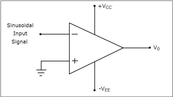
The operation of the inverting comparator shown above is discussed below −
During the positive half cycle of the sinusoidal input signal, the voltage present at the inverting terminal of op-amp is greater than zero volts. Hence, the output value of the inverting comparator will be equal to $-V_{sat}$ during positive half cycle of the sinusoidal input signal.
Similarly, during the negative half cycle of the sinusoidal input signal, the voltage present at the inverting terminal of the op-amp is less than zero volts. Hence, the output value of the inverting comparator will be equal to $+V_{sat}$ during negative half cycle of the sinusoidal input signal.
The following figure shows the input and output waveforms of an inverting comparator, when the reference voltage is zero volts.
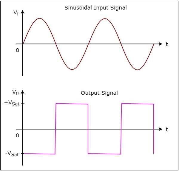
In the figure shown above, we can observe that the output transitions either from $-V_{sat}$ to $+V_{sat}$ or from $+V_{sat}$ to $-V_{sat}$ whenever the sinusoidal input signal is crossing zero volts. In other words, output changes its value when the input is crossing zero volts. Hence, the above circuit is also called as inverting zero crossing detector.
Non-Inverting Comparator
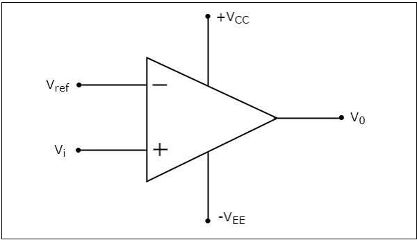
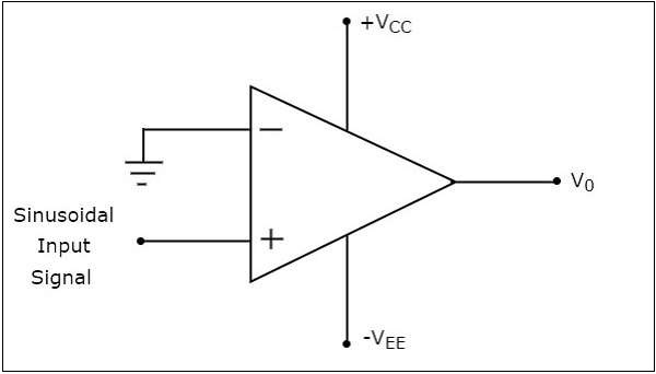
A non-inverting comparator is an op-amp based comparator for which a reference voltage is applied to its inverting terminal and the input voltage is applied to its non-inverting terminal. This op-amp based comparator is called as non-inverting comparator because the input voltage, which has to be compared is applied to the non-inverting terminal of the op-amp.
The circuit diagram of a non-inverting comparator is shown in the following figure
The operation of a non-inverting comparator is very simple. It produces one of the two values, $+V_{sat}$ and $-V_{sat}$ at the output based on the values of input voltage $V_{t}$ and the reference voltage $+V_{ref}$.
The output value of a non-inverting comparator will be $+V_{sat}$, for which the input voltage $V_{i}$ is greater than the reference voltage $+V_{ref}$.
The output value of a non-inverting comparator will bee $-V_{sat}$, for which the input voltage $V_{i}$ is less than the reference voltage $+V_{ref}$.
Example
Let us draw the output wave form of a non-inverting comparator, when a sinusoidal input signal and reference voltage of zero volts are applied to the non-inverting and inverting terminals of the op-amp respectively.
The operation of a non-inverting comparator is explained below −
During the positive half cycle of the sinusoidal input signal, the voltage present at the non-inverting terminal of op-amp is greater than zero volts. Hence, the output value of a non-inverting comparator will be equal to $+V_{sat}$ during the positive half cycle of the sinusoidal input signal.
Similarly, during the negative half cycle of the sinusoidal input signal, the voltage present at the non-inverting terminal of op-amp is less than zero volts. Hence, the output value of non-inverting comparator will be equal to $-V_{sat}$ during the negative half cycle of the sinusoidal input signal.
The following figure shows the input and output waveforms of a non-inverting comparator, when the reference voltage is zero volts.
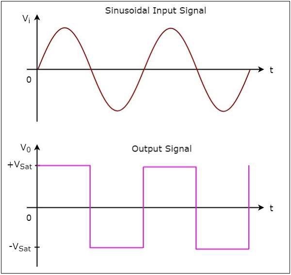
From the figure shown above, we can observe that the output transitions either from $+V_{sat}$ to $-V_{sat}$ or from $-V_{sat}$ to $+V_{sat}$ whenever the sinusoidal input signal crosses zero volts. That means, the output changes its value when the input is crossing zero volts. Hence, the above circuit is also called as non-inverting zero crossing detector.