- Linear Integrated Circuits Applications
- Home
- Basics of Integrated Circuits Applications
- Basics Operational Amplifier
- Op-Amp applications
- Arithmetic Circuits
- Differentiator & Integrator
- Converters Of Electrical Quantities
- Comparators
- Log & Anti-Log Amplifiers
- Rectifiers
- Clippers
- Clampers
- Active Filters
- Sinusoidal Oscillators
- Waveform Generators
- 555 Timer
- Phase Locked Loop Ic
- Voltage Regulators
- Data Converters
- Digital to Analog Converters
- DAC Example Problem
- Direct Type ADCs
- Indirect Type ADC
- Useful Resources
- Quick Guide
- Useful Resources
- Discussion
Clampers
In the previous chapter, we discussed about clippers. Now, let us discuss about other type of wave shaping circuits, namely clampers.
Op-amp based Clampers
A clamper is an electronic circuit that produces an output, which is similar to the input but with a shift in the DC level. In other words, the output of a clamper is an exact replica of the input. Hence, the peak to peak amplitude of the output of a clamper will be always equal to that of the input.
Clampers are used to introduce or restore the DC level of input signal at the output. There are two types of op-amp based clampers based on the DC shift of the input.
- Positive Clamper
- Negative Clamper
This section discusses about these two types of clampers in detail.
Positive Clamper
A positive clamper is a clamper circuit that produces an output in such a way that the input signal gets shifted vertically by a positive DC value.
The circuit diagram of a positive clamper is shown in the following figure −
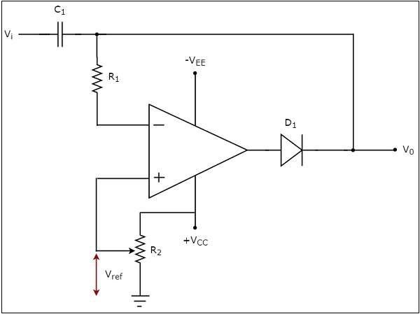
In the above circuit, a sinusoidal voltage signal, $V_{i}$ is applied to the inverting terminal of op-amp through a network that consists of a capacitor $C_{1}$ and a resistor $R_{1}$. That means, AC voltage signal is applied to the inverting terminal of the op-amp.
The DC reference voltage $V_{ref}$ is applied to the non-inverting terminal of the op-amp. The value of reference voltage $V_{ref}$ can be chosen by varying the resistor $R_{2}$. In this case, we will get a reference voltage $V_{ref}$ of a positive value.
The above circuit produces an output, which is the combination (resultant sum) of the sinusoidal voltage signal $V_{i}$ and the reference voltage $V_{ref}$. That means, the clamper circuit produces an output in such a way that the sinusoidal voltage signal $V_{i}$ gets shifted vertically upwards by the value of reference voltage $V_{ref}$.
The input wave form and the corresponding output wave form of positive clamper are shown in above figure −
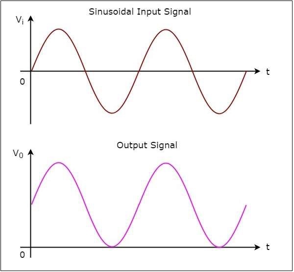
From the figure above, you can observe that the positive clamper shifts the applied input waveform vertically upward at the output. The amount of shift will depend on the value of the DC reference voltage.
Negative Clamper
A negative clamper is a clamper circuit that produces an output in such a way that the input signal gets shifted vertically by a negative DC value.
The circuit diagram of negative clamper is shown in the following figure −
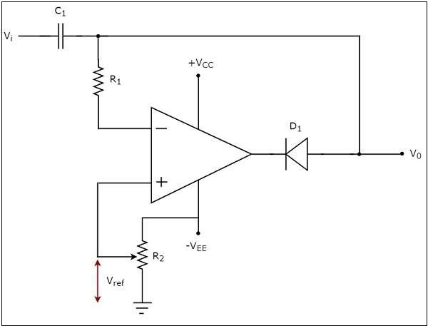
In the above circuit, a sinusoidal voltage signal $V_{i}$ is applied to the inverting terminal of the op-amp through a network that consists of a capacitor C1 and resistor $R_{1}$. That means, AC voltage signal is applied to the inverting terminal of the op-amp.
The DC reference voltage $V_{ref}$ is applied to the non-inverting terminal of the op-amp.The value of reference voltage $V_{ref}$ can be chosen by varying the resistor $R_{2}$. In this case,we will get reference voltage $V_{ref}$ of a negative value.
The above circuit produces an output, which is the combination (resultant sum) of sinusoidal voltage signal $V_{i}$ and reference voltage $V_{ref}$. That means, the clamper circuit produces an output in such a way that the sinusoidal voltage signal $V_{i}$ gets shifted vertically downwards by the value of reference voltage $V_{ref}$.
The input wave form and the corresponding output wave form of a negative clamper are shown in the following figure −
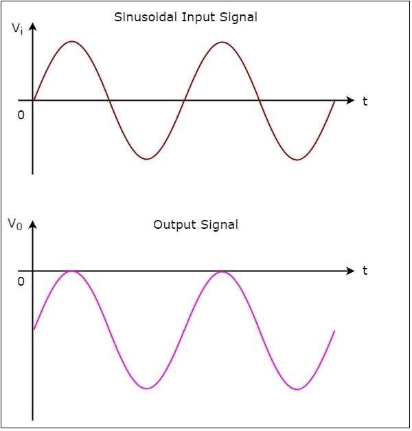
We can observe from the output that the negative clamper shifts the applied input waveform vertically downward at the output. The amount of shifting will depend on the value of DC reference voltage.