- Linear Integrated Circuits Applications
- Home
- Basics of Integrated Circuits Applications
- Basics Operational Amplifier
- Op-Amp applications
- Arithmetic Circuits
- Differentiator & Integrator
- Converters Of Electrical Quantities
- Comparators
- Log & Anti-Log Amplifiers
- Rectifiers
- Clippers
- Clampers
- Active Filters
- Sinusoidal Oscillators
- Waveform Generators
- 555 Timer
- Phase Locked Loop Ic
- Voltage Regulators
- Data Converters
- Digital to Analog Converters
- DAC Example Problem
- Direct Type ADCs
- Indirect Type ADC
- Useful Resources
- Quick Guide
- Useful Resources
- Discussion
Waveform Generators
A waveform generator is an electronic circuit, which generates a standard wave. There are two types of op-amp based waveform generators −
- Square wave generator
- Triangular wave generator
This chapter discusses each of these op-amp based waveform generators in detail.
Square Wave Generator
A square wave generator is an electronic circuit which generates square wave. This section discusses about op-amp based square wave generators.
The circuit diagram of a op-amp based square wave generator is shown in the following figure
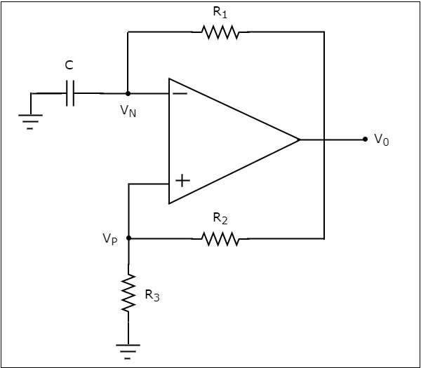
Observe that in the circuit diagram shown above, the resistor $R_{1}$ is connected between the inverting input terminal of the op-amp and its output of op-amp. So, the resistor $R_{1}$ is used in the negative feedback. Similarly, the resistor $R_{2}$ is connected between the noninverting input terminal of the op-amp and its output. So, the resistor $R_{2}$ is used in the positive feedback path.
A capacitor C is connected between the inverting input terminal of the op-amp and ground. So, the voltage across capacitor C will be the input voltage at this inverting terminal of op-amp. Similarly, a resistor $R_{3}$ is connected between the non-inverting input terminal of the op-amp and ground. So, the voltage across resistor $R_{3}$ will be the input voltage at this non-inverting terminal of the op-amp.
The operation of a square wave generator is explained below −
Assume, there is no charge stored in the capacitor initially. Then, the voltage present at the inverting terminal of the op-amp is zero volts. But, there is some offset voltage at non-inverting terminal of op-amp. Due to this, the value present at the output of above circuit will be $+V_{sat}$.
Now, the capacitor C starts charging through a resistor $R_{1}$. The value present at the output of the above circuit will change to $-V_{sat}$, when the voltage across the capacitor C reaches just greater than the voltage (positive value) across resistor $R_{3}$.
The capacitor C starts discharging through a resistor $R_{1}$, when the output of above circuit is $-V_{sat}$. The value present at the output of above circuit will change to $+V_{sat}$,when the voltage across capacitor C reaches just less than (more negative) the voltage (negative value) across resistor $R_{3}$.
Thus, the circuit shown in the above diagram will produce a square wave at the output as shown in the following figure −
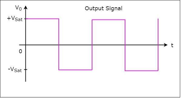
From the above figure we can observe that the output of square wave generator will have one of the two values: $+V_{sat}$ and $-V_{sat}$. So, the output remains at one value for some duration and then transitions to another value and remains there for some duration. In this way, it continues.
Triangular Wave Generator
A triangular wave generator is an electronic circuit, which generates a triangular wave. The block diagram of a triangular wave generator is shown in the following figure −
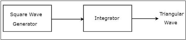
The block diagram of a triangular wave generator contains mainly two blocks: a square wave generator and an integrator. These two blocks are cascaded. That means, the output of square wave generator is applied as an input of integrator. Note that the integration of a square wave is nothing but a triangular wave.
The circuit diagram of an op-amp based triangular wave generator is shown in the following figure −
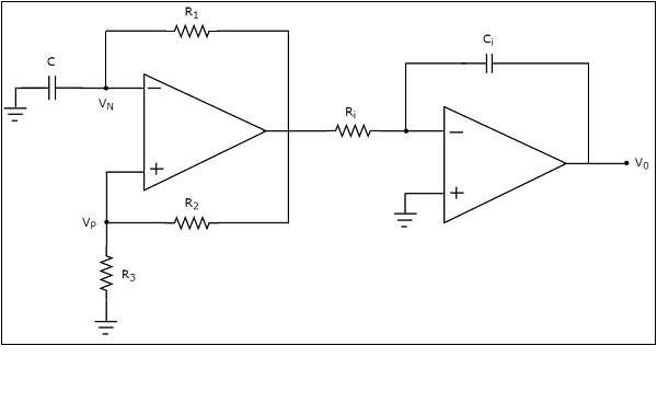
We have already seen the circuit diagrams of a square wave generator and an integrator. Observe that we got the above circuit diagram of an op-amp based triangular wave generator by replacing the blocks with the respective circuit diagrams in the block diagram of a triangular wave generator.