- Linear Integrated Circuits Applications
- Home
- Basics of Integrated Circuits Applications
- Basics Operational Amplifier
- Op-Amp applications
- Arithmetic Circuits
- Differentiator & Integrator
- Converters Of Electrical Quantities
- Comparators
- Log & Anti-Log Amplifiers
- Rectifiers
- Clippers
- Clampers
- Active Filters
- Sinusoidal Oscillators
- Waveform Generators
- 555 Timer
- Phase Locked Loop Ic
- Voltage Regulators
- Data Converters
- Digital to Analog Converters
- DAC Example Problem
- Direct Type ADCs
- Indirect Type ADC
- Useful Resources
- Quick Guide
- Useful Resources
- Discussion
Rectifiers
AC and DC are two frequent terms that you encounter while studying the flow of electrical charge. Alternating Current (AC) has the property to change its state continuously. For example, if we consider a sine wave, the current flows in one direction for positive half cycle and in the opposite direction for negative half cycle. On the other hand, Direct Current (DC) flows only in one direction.
An electronic circuit, which produces either DC signal or a pulsated DC signal, when an AC signal is applied to it is called as a rectifier. This chapter discusses about op-amp based rectifiers in detail.
Types of Rectifiers
Rectifiers are classified into two types: Half wave rectifier and Full wave rectifier. This section discusses about these two types in detail.
Half wave Rectifier
A half wave rectifier is a rectifier that produces positive half cycles at the output for one half cycle of the input and zero output for the other half cycle of the input.
The circuit diagram of a half wave rectifier is shown in the following figure.
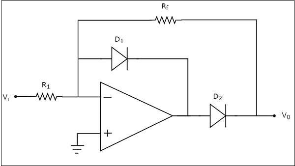
Observe that the circuit diagram of a half wave rectifier shown above looks like an inverting amplifier, with two diodes D1 and D2 in addition.
The working of the half wave rectifier circuit shown above is explained below
For the positive half cycle of the sinusoidal input, the output of the op-amp will be negative. Hence, diode D1 will be forward biased.
When diode D1 is in forward bias, output voltage of the op-amp will be -0.7 V. So, diode D2 will be reverse biased. Hence, the output voltage of the above circuit is zero volts.
Therefore, there is no (zero) output of half wave rectifier for the positive half cycle of a sinusoidal input.
For the negative half cycle of sinusoidal input, the output of the op-amp will be positive. Hence, the diodes D1 and D2 will be reverse biased and forward biased respectively. So, the output voltage of above circuit will be −
$$V_0=-\left(\frac{R_f}{R_1}\right)V_1$$
Therefore, the output of a half wave rectifier will be a positive half cycle for a negative half cycle of the sinusoidal input.
Wave forms
The input and output waveforms of a half wave rectifier are shown in the following figure
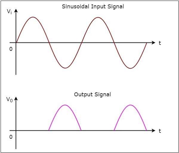
As you can see from the above graph, the half wave rectifier circuit diagram that we discussed will produce positive half cycles for negative half cycles of sinusoidal input and zero output for positive half cycles of sinusoidal input
Full wave Rectifier
A full wave rectifier produces positive half cycles at the output for both half cycles of the input.
The circuit diagram of a full wave rectifier is shown in the following figure −
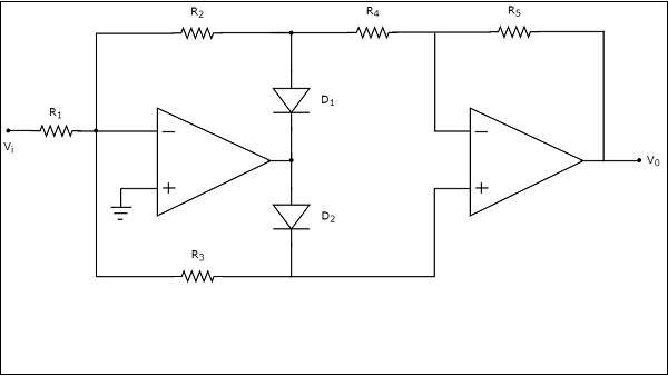
The above circuit diagram consists of two op-amps, two diodes, D1 & D2 and five resistors, R1 to R5. The working of the full wave rectifier circuit shown above is explained below −
For the positive half cycle of a sinusoidal input, the output of the first op-amp will be negative. Hence, diodes D1 and D2 will be forward biased and reverse biased respectively.
Then, the output voltage of the first op-amp will be −
$$V_{01}=-\left(\frac{R_2}{R_1}\right)V_i$$
Observe that the output of the first op-amp is connected to a resistor R4, which is connected to the inverting terminal of the second op-amp. The voltage present at the non-inverting terminal of second op-amp is 0 V. So, the second op-amp with resistors, R4 and R4 acts as an inverting amplifier.
The output voltage of the second op-amp will be
$$V_0=-\left(\frac{R_5}{R_4}\right)V_{01}$$
Substituting the value of $V_{01}$ in the above equation, we get −
$$=>V_{0}=-\left(\frac{R_5}{R_4}\right)\left \{ -\left(\frac{R_2}{R_1}\right)V_{i} \right \}$$
$$=>V_{0}=\left(\frac{R_2R_5}{R_1R_4}\right)V_{i}$$
Therefore, the output of a full wave rectifier will be a positive half cycle for the positive half cycle of a sinusoidal input. In this case, the gain of the output is $\frac{R_2R_5}{R_1R_4}$. If we consider $R_{1}=R_{2}=R_{4}=R_{5}=R$, then the gain of the output will be one.
For the negative half cycle of a sinusoidal input, the output of the first op-amp will be positive. Hence, diodes D1 and D2 will be reverse biased and forward biased respectively.
The output voltage of the first op-amp will be −
$$V_{01}=-\left(\frac{R_3}{R_1}\right)V_{i}$$
The output of the first op-amp is directly connected to the non-inverting terminal of the second op-amp. Now, the second op-amp with resistors, R4 and R5 acts as a non-inverting amplifier.
The output voltage of the second op-amp will be −
$$V_{0}=\left(1+\frac{R_5}{R_4}\right)V_{01}$$
Substituting the value of $V_{01}$ in the above equation, we get
$$=>V_{0}=\left(1+\frac{R_5}{R_4}\right) \left\{-\left(\frac{R_3}{R_1}\right)V_{i}\right \} $$
$$=>V_{0}=-\left(\frac{R_3}{R_1}\right)\left(1+\frac{R_5}{R_4}\right)V_{i}$$
Therefore, the output of a full wave rectifier will be a positive half cycle for the negative half cycle of sinusoidal input also. In this case, the magnitude of the gain of the output is $\left(\frac{R_3}{R_1}\right)\left(1+\frac{R_5}{R_4}\right)$. If we consider $R_{1}=2R_{3}=R_{4}=R_{5}=R$ then the gain of the output will be one.
The input and output waveforms of a full wave rectifier are shown in the following figure
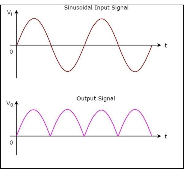
As you can see in the above figure, the full wave rectifier circuit diagram that we considered will produce only positive half cycles for both positive and negative half cycles of a sinusoidal input.