- TSSN - Home
- TSSN - Introduction
- TSSN - Switching Systems
- Elements of a Switching System
- TSSN - Strowger Switching System
- TSSN - Switching Mechanisms
- TSSN - Common Control
- TSSN - Touch-tone Dial Telephone
- TSSN - Crossbar Switching
- Crossbar Switch Configurations
- TSSN - Crosspoint Technology
- TSSN - Stored Program Control
- TSSN - Software Architecture
- TSSN - Switching Techniques
- TSSN - Time Division Switching
- TSSN - Telephone Networks
- TSSN - Signaling Techniques
- TSSN - ISDN
TSSN - Switching Systems
In this chapter, we will understand how the switching systems work. A Switching system can be understood as a collection of switching elements arranged and controlled in such a way as to set up a common path between any two distant points. The introduction of switching systems reduced the complexity of wiring and made the telephony hassle-free.
Classification of Switching Systems
In the early stages of telecommunication systems, the process and stages of switching, played an important to make or break connections. At the initial stages, the switching systems were operated manually. These systems were later automated. The following flowchart shows how the switching systems were classified.
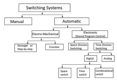
The switching systems in the early stages were operated manually. The connections were made by the operators at the telephone exchanges in order to establish a connection. To minimize the disadvantages of manual operation, automatic switching systems were introduced.
The Automatic switching systems are classified as the following −
Electromechanical Switching Systems − Here, mechanical switches are electrically operated.
Electronic Switching Systems − Here, the usage of electronic components such as diodes, transistors and ICs are used for the switching purposes.
Electromechanical Switching Systems
The Electromechanical switching systems are a combination of mechanical and electrical switching types. The electrical circuits and the mechanical relays are deployed in them. The Electromechanical switching systems are further classified into the following.
Step-by-step
The Step-by-step switching system is also called the Strowger switching system after its inventor A B Strowger. The control functions in a Strowger system are performed by circuits associated with the switching elements in the system.
Crossbar
The Crossbar switching systems have hard-wired control subsystems which use relays and latches. These subsystems have limited capability and it is virtually impossible to modify them to provide additional functionalities.
Electronic Switching Systems
The Electronic Switching systems are operated with the help of a processor or a computer which control the switching timings. The instructions are programmed and stored on a processor or computer that control the operations. This method of storing the programs on a processor or computer is called the Stored Program Control (SPC) technology. New facilities can be added to a SPC system by changing the control program.
The switching scheme used by the electronic switching systems may be either Space Division Switching or Time Division Switching. In space division switching, a dedicated path is established between the calling and the called subscribers for the entire duration of the call. In time division switching, sampled values of speech signals are transferred at fixed intervals.
The time division switching may be analog or digital. In analog switching, the sampled voltage levels are transmitted as they are. However, in binary switching, they are binary coded and transmitted. If the coded values are transferred during the same time interval from input to output, the technique is called Space Switching. If the values are stored and transferred to the output at a time interval, the technique is called Time Switching. A time division digital switch may also be designed by using a combination of space and time switching techniques.
Telecommunication Network
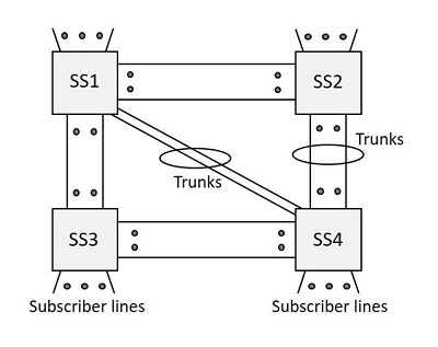
A Telecommunication network is a group of systems that establishes a distant call. The switching systems are part of a telecommunication network.
The switching stations provide connection between different subscribers. Such switching systems can be grouped to form a telecommunication network. The switching systems are connected using lines called the Trunks. The lines that run to the Subscriber premises are called the Subscriber Lines.
The following figure shows a telecommunication network.
From the early to the later stages of the 20th Century (1900-80), when a person needed to make a distant call, the call was first routed to the operator at the nearest switching center and then the number and location of the called subscriber was noted down. Here, the job of the operator was to establish a call to the remote switching center and then recall the calling subscriber to establish the connection. This system of making calls was called the Trunk call system.
For example, a person at Hyderabad can book a trunk call to Mumbai and wait for the operator to call back when the operator establishes connection through the trunk lines and the switching systems.
Basics of a Switching System
In this section, we will learn about the different components and terms used in switching systems.
Inlets and Outlets
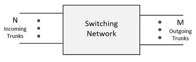
The set of input circuits of an exchange are called Inlets and the set of output circuits are called the Outlets. The primary function of a switching system is to establish an electrical path between a given inlet-outlet pair.
Usually, N indicates the inlets and the outlets are indicated by M. So, a switching network has N inlets and M outlets.
Switching Matrix
The hardware used to establish connection between inlets and outlets is called the Switching Matrix or the Switching Network. This switching network is the group of connections formed in the process of connecting inlets and outlets. Hence, it is different from the telecommunication network mentioned above.
Types of Connections
There are four types of connections that can be established in a telecommunication network. The connections are as follows −
- Local call connection between two subscribers in the system.
- Outgoing call connection between a subscriber and an outgoing trunk.
- Incoming call connection between an incoming trunk and a local subscriber.
- Transit call connection between an incoming trunk and an outgoing trunk.
Folded Network
When the number of inlets is equal to the number of outlets for a switching network, such a network is called the Symmetric Network, which means N=M. A network where the outlets are connected to the inlets, is called the Folded Network.
In a Folded Network, the N number of inlets which come as outlets are again folded back to the inlets. Nevertheless, the switching network provides connections to the inlets and outlets as per the requirement. The following figure will help you understand how the Switching Network works.
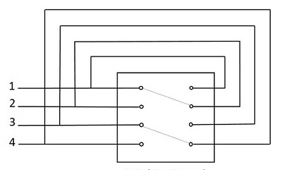
As one connection can be given to one line per time, only N/2 connections are established for N inlets of a folded network. Such a network can be called as Non-blocking network. In a non-blocking network, as long as the called subscriber is free, a calling subscriber will be able to establish a connection to the called subscriber.
In the above figure, only 4 subscribers were considered - where line 1 is busy with line 2 and line 3 is busy with line 4. While the call is in progress, there used to be no chance for making another call and hence, only a single connection was made. Hence for N inlets, only N/2 lines are connected.
At times, it might happen that the inlet and outlet connections are continuously used to make Transit calls through trunk lines only, but not among the local subscribers. The inlet and outlet connections if used in an Inter-exchange transmission such that the exchange does not support connection between local subscribers, then it is called the Transit Exchange. A switching network of such kind is called the Non-folded network. This is shown in the following figure −
Blocking Network
If there are no switching paths free in the network, the call requested will be denied, where the subscriber is said to be blocked and the network is called the Blocking Network. In a blocking network, the number of simultaneous switching paths is less than the maximum number of simultaneous conversations that can take place. The probability that a user may get blocked is called the Blocking Probability. A good design should ensure low blocking probability.
Traffic
The product of the calling rate and the average holding time is defined as the Traffic Intensity. The continuous sixty-minute period during which the traffic intensity is high is the Busy Hour. When the traffic exceeds the limit to which the switching system is designed, a subscriber experiences blocking.
Erlang
The traffic in a telecommunication network is measured by an internationally accepted unit of traffic intensity known as Erlang (E). A switching resource is said to carry one Erlang of traffic if it is continuously occupied through a given period of observation.
