- TSSN - Home
- TSSN - Introduction
- TSSN - Switching Systems
- Elements of a Switching System
- TSSN - Strowger Switching System
- TSSN - Switching Mechanisms
- TSSN - Common Control
- TSSN - Touch-tone Dial Telephone
- TSSN - Crossbar Switching
- Crossbar Switch Configurations
- TSSN - Crosspoint Technology
- TSSN - Stored Program Control
- TSSN - Software Architecture
- TSSN - Switching Techniques
- TSSN - Time Division Switching
- TSSN - Telephone Networks
- TSSN - Signaling Techniques
- TSSN - ISDN
TSSN - Crossbar Switch Configurations
In this chapter, we will discuss how the Crossbar switch configuration works. The Crossbar switch configurations are Non-blocking configurations, which have N2 switching elements for N subscribers and can make N/2 simultaneous conversations. The usage of Crosspoint depends upon the calling subscriber.
This is a modified Non-blocking scheme with Diagonal Crosspoint matrix as discussed above having N(N-1)/2 elements. The number of elements is same as that of a fully connected network. The connection in this method is established by first energizing the horizontal bar and then the vertical bar. However, this Non-blocking scheme has few disadvantages such as −
- Large number of switching elements are required.
- This is difficult to implement in practice.
- This is neither a cost-effective process.
In order to overcome these disadvantages, the blocking Crossbar switching was introduced.
Blocking Crossbar Switches
The main aim of blocking Crossbar switches is to reduce the number of Crosspoint switches. There are single stage and multi-stage switches. The number of Crosspoint switches can be reduced with the help of two different methodologies. In the first method, two subscribers share one vertical bar. With this, the number of bars will be reduced but the number of Crosspoint switches remain the same. The second method is where all the subscribers share a number of vertical bars. With this, the number of bars and Crosspoint switches are reduced.
Method 1
This method contains 2NK switches, where N is the number of subscribers and K is the number of simultaneous connections. Four bars operate to establish a connection. If a connection has to be established between A and B, then the horizontal bar A is energized first and then one of the free vertical bars say P is energized. Now, the Crosspoint AP is latched. If the horizontal bar B is energized now, BP will not be latched, as the P vertical is energized before B was energized. To connect A and B, we need another vertical Crossbar which should electrically correspond to the vertical bar P, which is P as shown in the following figure. When this P is energized after B, the Crosspoint BP is latched and a connection between A and B is established.
The connections are as shown in the following figure.
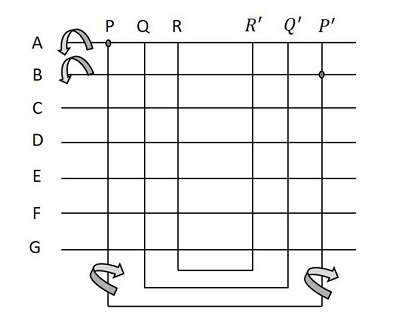
Hence, the steps associated with the establishment of connection follows a sequence −
- Energize horizontal bar A
- Energize free vertical bar P
- De-energize horizontal bar A
- Energize horizontal bar B
- Energize free vertical bar P (associated with P)
De-energize horizontal bar B
Method 2
This method contains NK switches, where N is the number of subscribers and K is the number of simultaneous connections. Here, three bars operate to establish a connection. If a connection has to be established between A and B, then the horizontal bars A and B are energized first and then one of the free vertical bars say P is energized. Now, the connection is established using one vertical bar P only instead of two bars. The horizontal bars A and B are de-energized now.
The connections are as shown in the following figure.
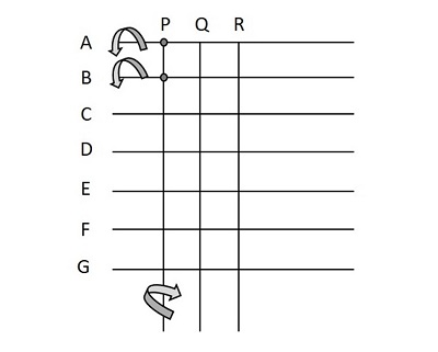
Hence, the establishment of connection follows a sequence −
- Energize horizontal bars A and B
- Energize free vertical bar P
- De-energize horizontal bars A and B
Transfer Line Support
In this section, we will discuss how the Transfer Line Support works. Both of the above discussed blocking and non-blocking type Crossbar switches can support transfer lines. This is done by introducing additional vertical Crossbars and Crosspoint switches.
There are two methods to introduce additional vertical Crossbars and Crosspoint switches
- Internal non-blocking and external blocking
- Blocking both local and external
The internal non-blocking and external blocking method is as shown in the figure below.
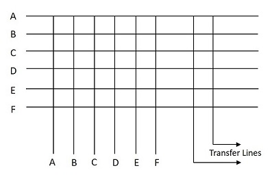
The switch shown in internal non-blocking has two transfer lines. The number of Crosspoint switches in this case is N(N+L), where N is the number of subscribers, L is the number of transfer lines.
The method of blocking both local and external is as shown in the figure below.
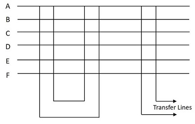
The switch shown in the above figure is blocking both internally and externally with two simultaneous internal and two simultaneous external calls. The number of Crosspoint switches in this case is N(2K+L), where N is the number of subscribers, L is the number of transfer lines and K is the number of simultaneous calls that can be supported locally.
