- TSSN - Home
- TSSN - Introduction
- TSSN - Switching Systems
- Elements of a Switching System
- TSSN - Strowger Switching System
- TSSN - Switching Mechanisms
- TSSN - Common Control
- TSSN - Touch-tone Dial Telephone
- TSSN - Crossbar Switching
- Crossbar Switch Configurations
- TSSN - Crosspoint Technology
- TSSN - Stored Program Control
- TSSN - Software Architecture
- TSSN - Switching Techniques
- TSSN - Time Division Switching
- TSSN - Telephone Networks
- TSSN - Signaling Techniques
- TSSN - ISDN
TSSN - Common Control Subsystem
In this chapter, we will discuss how the Common Control Subsystem works in Telecommunication Switching Systems and Networks.
In order to establish calls between different exchanges, which may further lead to a long distance trunk call, the Crossbar switching system was developed and the first patent was given in 1915. However, AT&T developed the first Crossbar switching system in 1938. The Crossbar switching system introduced the Common Control Subsystem in its switching system.
To understand this, let us have an idea on the problem created by Multi-exchange network of the Strowger system.
Multi-Exchange Network
When a subscriber belonging to a particular network has to be contacted, a number of ways can help you contact the particular exchange; also, there is not one but any exchanges present in the route.
In a Multi exchange network, the routes used to establish connection with a particular subscriber differs from time to time. In the Strowger exchange following the Multi-exchange network, the subscriber has to be more concerned with the routing. A subscriber should have the details of all the numbers of exchanges present in the route. There may arise situations where a subscriber may be required to establish a connection on other routes; this becomes cumbersome at times.
The following figure is an example of the topology of a Multi-exchange network.
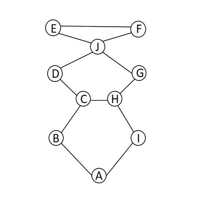
The level is reserved in each Strowger exchange, where the outgoing calls are connected to neighboring exchanges. These exchanges are contacted as per the exchange numbers dialed, when the calls are made.
Hence, the disadvantages of implementing Multi-Exchange network in switching are −
The subscriber identity number is changed depending on the calling route.
The user must have knowledge on the topology of the network and the numbers of the exchanges present in it.
The number and size of the called subscriber varies depending upon the exchange from where the call originates.
In order to overcome these problems, the common control subsystem was introduced.
Common Control Subsystem
In order to avoid the complication and to make it easier for a subscriber to place a call, two main ideas were implemented by the Common Control Sub system. The ideas are listed below −
The routing of the call should be done by the exchange, but not by the numbers dialed.
A Unique Identification Number should be allotted to the subscriber. The UIN contains the number of the exchange of the subscriber and the number indicating the line of the subscriber.
A Unique Identification Number should be allotted to the subscriber. The UIN contains the number of the exchange of the subscriber and the number indicating the line of the subscriber.
Exchange Identifier + Subscriber Line Identifier
This is a combination of STD (Subscriber Trunk Dialing) code and the subscribers number; consider this as the physical line address. Every user is assigned a logical number irrespective of the physical line number. An Address translation mechanism translates the logical address to actual physical address for connection establishment. The call processing takes place independent of the switching network.
A Director system is employed in the common control sub system. As soon as the translated digits are transmitted, the Director is free to process another call and is not involved in maintaining the circuit for the conversation.
The following figure shows the diagram of the Common Control Subsystem, which contains Call Processing Sub system, Charging Circuits, Operation Control, Maintenance Control and Event Monitor.
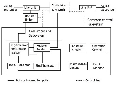
The above block diagram is a simple indication of the common control switching system. The control functions in a switching system can be categorized as the following.
Event Monitoring
Event Monitoring Section of the Control Subsystem monitors the events occurring outside the exchange at the line units, trunk junctures and inter exchange signaling and sender/receiver units. The events at the line units are - call request and call release. The control of relays to establish connection to the required line is an event at the junctures. There is control of relays between the exchanges for connection and also for signaling the required tones both to the sender and receiver circuits at the inter exchange. This event monitoring may be distributed.
Call Processing
The Call Processing units contain digit receiver and storage register, which receive and store the dialing number from the calling party. The units also contain the initial and final translators. The Initial translator is the Office Code translator that determines the route for the call through the network or charging method or rate. The Final translator is the Subscriber Code translator which determines the line unit to which a call must be connected and category of the called line. The Register Sender transfers the route digit and dialed digit using proper signaling, depending on the requirements of the destination exchange.
Charging
This is related to the charges levied on the calls made. It depends upon the type of subscriber and the service of the subscriber. For example, some services like emergency lines or fault repairs are free of charge; a few commercial services also may offer charge-free services.
Operation and Maintenance
The control and operation of the switching network with two main techniques known as Map-in-memory and Map-in-network.
Map-in-Memory
The path in this technique is determined by marking the switching elements at different stages in accordance with a set of binary data defining the path, whereas the control unit supplies the data. At this stage, the command for the actual connection of the path is given. This Map-in-memory technique is present in Stored Program Control.
Map-in-Network
In this technique, the Path finding may be carried out at the level of common control unit, where it marks the inlet and outlet to be connected and the actual path is determined by the switching network. This Map-in-Network technique is common in Crossbar exchanges using markers for control.
The administration and maintenance of a switching system, involves activities such as laying the new subscriber lines and trunks into service, modifying subscriber service entitlements and changing routing plans based on the network status, which are performed with the coordination of control systems. Maintenance personnel do the maintenance activities such as supervision for proper functioning, performing tests and making measurements for different line parameters.
