- TSSN - Home
- TSSN - Introduction
- TSSN - Switching Systems
- Elements of a Switching System
- TSSN - Strowger Switching System
- TSSN - Switching Mechanisms
- TSSN - Common Control
- TSSN - Touch-tone Dial Telephone
- TSSN - Crossbar Switching
- Crossbar Switch Configurations
- TSSN - Crosspoint Technology
- TSSN - Stored Program Control
- TSSN - Software Architecture
- TSSN - Switching Techniques
- TSSN - Time Division Switching
- TSSN - Telephone Networks
- TSSN - Signaling Techniques
- TSSN - ISDN
TSSN - Strowger Switching System
In this chapter, we will discuss how the Strowger Switching system works. The first ever automatic telephone switching was developed by Almon B Strowger. As the operator at the Manual telephone exchange was the wife of his competitor and was diverting all the business, Strowger thought of developing a switching system, which does not require an operator. This led to the invention of the automatic switching system developed by Strowger.
The Strowger Switching system is also called the step-by-step switching system as the connections are established in a step-by-step manner.
Automatic Switching System
The Manual Switching system requires an operator who after receiving a request, places a call. Here, the operator is the sole in-charge for establishing or releasing the connections. The privacy of the calls and the details of the called and the calling subscribers are at stake.
Overcoming the disadvantages of Manual Switching systems, the Automatic Switching systems come with the following advantages −
Language barriers will not affect the request for connection.
Higher degree of privacy is maintained.
Faster establishment and release of calls is done.
Number of calls made in a given period can be increased.
Calls can be made irrespective of the load on the system or the time of the day.
Let us now throw some light on how a call is made and how dialing is done without the help of an operator.
Dialing
Unlike in Manual Switching system, an automatic switching system requires a formal numbering plan or addressing scheme to identify the subscribers. Numbering plan is where a number identifies a subscriber, is more widely used than the addressing scheme in which a subscriber is identified by the alpha numerical strings. So, there needs to be a mechanism to transmit the identity of the called subscriber to the exchange.
This mechanism should be present in the telephone set, in order to connect the call automatically to the required subscriber. The methods prevalent for this purpose are Pulse Dialing and Multi Frequency Dialing. Of them, the Pulse dialing is the most commonly used form of dialing till date.
Pulse Dialing
As the name implies, the digits that are used to identify the subscribers are represented by a train of pulses. The number of pulses in a train is equal to the digit value it represents except in the case of zero, which is represented by 10 pulses. Successive digits in a number are represented by a series of pulse trains. These pulses have equal number of time intervals and the number of pulses produced will be according to the number dialed.
Two successive trains are distinguished from one another by a pause in between them, known as the Inter-digit gap. The pulses are generated by alternately breaking and making the loop circuit between the subscriber and the exchange. An example pulse train is shown in the following figure.
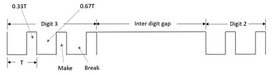
The above figure shows the pulsating pattern. The pulse rate is usually 10 pulses per second with a 10 percent of tolerance. The gap between the digits, which is called the Inter-digit gap is at least 200ms.
The pulse dialing pattern in recent times employs the duty ratio (ratio between the pulse width and the time period of the waveform) of the pulse as 33 percent nominally and there exists an upper limit for the inter-digit gap.
Rotary Dial Telephone
In this section, we will learn about what the Rotary Dial Telephone is and how it works. To start with, we will discuss the drawbacks that were prevalent before the invention of the Rotary Dial Telephone.
The pulse dialing technique is where there is making and breaking of the subscriber loops. This might disturb and affect the performance of speaker, microphone and bell contained in the telephone. In addition, the dialing timings should not affect the timing of the pulse train as this will lead to the dialing of a wrong number.
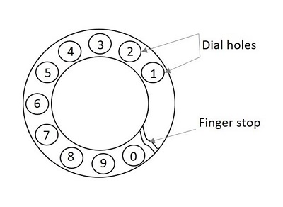
The Rotary Dial Telephone came into existence to solve the problems prevailing then. The microphone and the loudspeaker are combined and placed in the receiver set. The set has a finger plate the arrangement of which makes the dialing time appropriate. The below figure shows how a rotary dial looks like.

The dial is operated by placing the finger in the hole appropriate to the digit to be dialed. Now, drawing the fingerplate round in the clockwise direction to the finger stop position and letting the dial free by withdrawing the finger, makes a number dialed. The fingerplate and the associated mechanism now return to the rest position under the influence of a spring. The dial is ready for the next number.
The dial pulses are produced during the return travel of the fingerplate, thus eliminating the human element in pulse timings. The following figure shows the dial holes and finger stop.
A rotary dial phone uses the following for implementing pulse dialing −
- Finger plate and spring
- Shaft, gear and Pinion wheel
- Pawl and ratchet mechanism
- Impulsing cam and suppressor cam or a trigger mechanism
- Impulsing contact
- Centrifugal governor and worm gear
- Transmitter, Receiver and bell by-pass circuits
Internal Mechanism
The cam mechanism or trigger mechanism helps in dialing. This mechanism is used in operating the Impulsing contact. Let us consider the operation of the rotary dial telephone using the cam mechanism. The following figure will help you understand the internal mechanism.
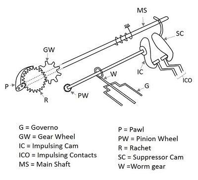
The suppressor cam helps in keeping the Impulsing cam away from the Impulsing contacts. When the rotary dial is in rest position, then the Impulsing contacts are away from the Impulsing cam. When a number is dialed, by placing the finger in the dial hole, which means the dial is displaced from its position, then the Impulsing contacts come near the Impulsing cam. This rotation of the finger plate, causes the rotation of the Main shaft.
As the dial is rotated in clockwise direction, the pawl slips over the ratchet during this clockwise rotation. The ratchet, gear wheel, pinion wheel and the governor are all stationary during the clockwise movement of the dial. When the dial returns, the pawl engages and rotates the ratchet.
All the gear wheel, pinion wheel, the governor rotate, and the uniformity in the speed of the rotation are maintained by the governor. The Impulsing cam, which is attached to a pinion shaft, now breaks and makes the Impulsing contacts that in turn causes the pulses in the circuit. The shape of the Impulsing cam is such that the break and make periods are in the ratio of 2:1. When the dial is about to reach the rest position, the suppressor cam again, moves the Impulsing contacts away from the Impulsing cam. This action of getting back to the rest position and waiting for the other number to be dialed creates a gap called the Inter-digit gap, the timing of which is independent of the pause that may occur between two successive digits, due to human dialing habit. This gap is also provided prior to the dialing of the first digit through a small change in the suppressor cam design.
The Pulse generated through this mechanism is then transmitted to the switching systems where the connection to the dialed number is established. The procedure of switching systems is discussed in a subsequent chapter. Meanwhile, let us have an idea on the signaling tones that are used to indicate the condition of the subscribers.
Signaling Tones
In this section, we will understand what are signaling tones and how these work. As the manual exchanges were replaced, the operator who used to communicate the calling subscribers regarding the situation of the called subscribers, needed to be replaced with different tones indicating different situations.
Consider the following five subscriber related signaling functions that are to be performed by the operator −
Respond to the calling subscriber that system is ready to receive the identification of the called party.
Inform the calling subscriber that the call is being established.
Ring the bell of the called party.
Inform the calling subscriber, if the called party is busy.
Inform the calling subscriber, if the called party line is unobtainable for some reason.
The function 2 is not signaled in the Strowger switching system. The signaling function 1 is fulfilled by sending a dial tone to the calling subscriber.
Dial Tone
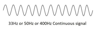
The dial tone is the signaling tone, which indicates that the exchange is ready to accept the dialed digits from the subscriber. The number should be dialed only when this signal is heard. Otherwise, the digits dialed before this signal will not be considered. This will lead to the dialing of a wrong number.
The dial tone is generally a 33 Hz or 50 Hz or 400 Hz continuous tone as shown below.
Ring Tone
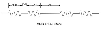
After dialing the number of the called party, when the line of the called party is obtained, the exchange control equipment sends out the ringing current to the telephone set of the called party, which is a familiar double-ring pattern.
Simultaneously, the control equipment sends out a ringing tone to the calling subscriber, which has a pattern similar to that of the ringing current. The two rings double-ring pattern are separated by a time gap of 0.2s and two double-ring patterns by a gap of 2s, as shown in the below figure.
Busy Tone
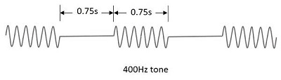
After dialing the required number, if the called subscriber or the lines at the exchange are not free to place a call, the calling subscriber is sent a busy tone indicating that the lines or the subscriber is busy; this is called a busy tone.
A busty tone of 400Hz signal with silence period in between. The burst and silence durations have the same value of 0.75s or 0.75s.
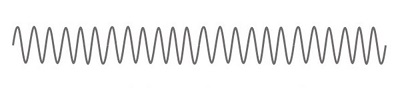
Number Unobtainable Tone
If the called party is out of order or disconnected or if an error in dialing leads to the selection of a spare line, such a situation is indicated using a continuous 400Hz signal, called as Number Unobtainable tone. The following illustration shows a continuous 400Hz signal.
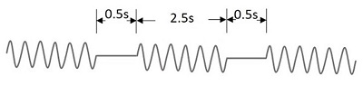
Routing Tone or Call-in-Progress Tone
When a subscriber call is routed through a number of different types of exchanges, one hears different call-in-progress tones as the call progresses through different exchanges. Such a signal is a 400Hz or 800Hz intermittent pattern. This signal has different patterns in different systems.
In electromechanical systems, it is usually 800Hz with 50 percent duty ratio and 0.5s ON/OFF period.
In analog electronic exchanges, it is a 400Hz pattern with 0.5s ON period and 2.5s OFF period.
In digital exchanges, it is 400Hz signal with 0.1s ON/OFF periods.
The signal for routing tone or call-in-progress tone is as shown below.
In order to overcome the problem of recognizing the difference in these tones for those who are not familiar with telephone signaling and for those who rarely make calls, voice recorded messages were introduced, later on.
