
- Semiconductor Devices - Home
- Introduction
- Atomic Combinations
- Conduction in Solid Materials
- Conductivity & Mobility
- Types of Semiconductor
- Doping in Semiconductors
- Junction Diodes
- Depletion Zone
- Barrier Potential
- Junction Biasing
- Leakage Current
- Diode Characteristics
- Light Emitting Diode
- Zener Diode
- Photo Diode
- Photovoltaic Cells
- Varactor Diode
- Bipolar Transistors
- Construction of a Transistor
- Transistor Biasing
- Configuration of Transistors
- Field Effect Transistors
- JFET Biasing
- Semiconductor Devices - MOSFET
- Operational Amplifiers
- Practical Op-Amps
- Semiconductor Devices - Integrator
- Differentiator
- Oscillators
- Feedback & Compensation
- Semiconductor Devices - Quick Guide
- Semiconductor Devices - Resources
- Semiconductor Devices - Discussion
Semiconductor Devices - Oscillators
An oscillator is an electronic circuit that generates sinusoidal oscillations known as sinusoidal oscillator. It converts input energy from a DC source into AC output energy of periodic waveform, at a specific frequency and is known amplitude. The characteristic feature of the oscillator is that it maintains its AC output.
The following figure shows an amplifier with feedback signal even in the absence of an externally applied input signal. A sinusoidal oscillator is essentially a form of feedback amplifier, where special requirements are placed on the voltage gain Av and the feedback networks β.
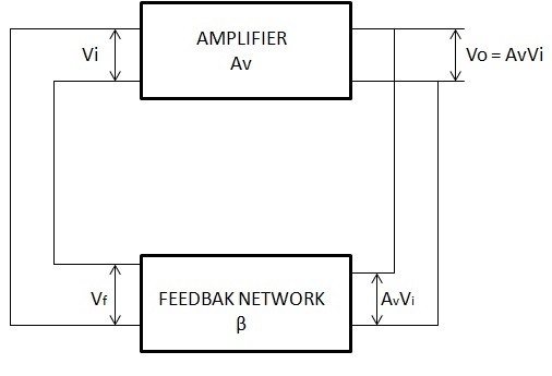
Consider the feedback amplifier of the above figure, where the feedback voltage Vf = βVO supplies the entire input voltage
$V_i = V_f = \beta V_0 = A_V\beta V_i$ (1)
$V_i = A_V\beta V_i$ Or $(1 - A_V\beta)V_i = 0$ (2)
If an output voltage is to be produced, the input voltage cannot be zero. Hence, for Vi to exist, Equation (2) requires that
$(1 - A_V\beta) = 0$ Or $A_V\beta = 1$ (3)
Equation (3) is known as Barkhausen criterion, which states two basic requirements for oscillation −
The voltage gain around the amplifier and feedback loop, called the loop gain, must be unity, or $A_V\beta = 1$.
The phase shift between $V_i$ and $V_f$, called the loop phase shift, must be zero.
If these two conditions are satisfied, the feedback amplifier of the above figure will generate a sinusoidal output waveform consistently.
Let us now discuss in detail about some typical oscillator circuits.
Phase Shift Oscillator
An oscillator circuit that follows the fundamental progress of a feedback circuit is the phase-shift oscillator. A phase-shift oscillator is shown in the following figure. The requirements for oscillation are that the loop gain (βA) should be greater than unity and the phase shift between input and output should be 360o.
Feedback is provided from the output of the RC network back to the amplifier input. The op-amp amplifier stage provides an initial 180-degree shift and the RC network introduces an additional amount of phase shift. At a specific frequency, the phase shift introduced by the network is exactly 180 degrees, so the loop will be 360 degrees and the feedback voltage is in phase input voltage.
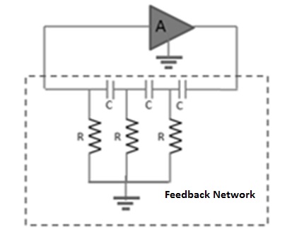
The minimum number of RC stages in the feedback network is three, as each section provides 60 degrees of phase shift. The RC oscillator is ideally suited to the range of audio frequencies, from a few cycles to approximately 100 KHz. At the higher frequencies, the network impedance becomes so low that it may seriously load the amplifier, thereby reducing its voltage gain below the required minimum value, and the oscillations will cease.
At low frequencies, the loading effect is not usually a problem and the required large resistance and capacitance values are readily available. Using the basic network analysis, frequency oscillation can be expressed as
$$f = \frac{1}{2\pi RC \sqrt{6}}$$
Wien Bridge Oscillator
A practical oscillator circuit uses an op-amp and RC bridge circuit, with the oscillator frequency set by the R and C components. The following figure shows a basic version of a Wien bridge oscillator circuit.
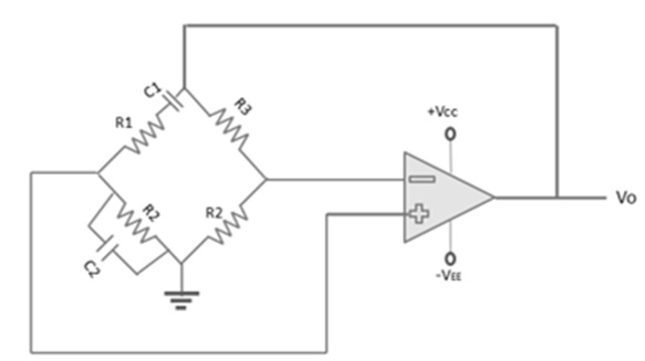
Note the basic bridge connection. Resistors R1 and R2 and capacitors C1 and C2 form the frequency-adjustment elements, while resistors R3 and R4 form part of the feedback path.
In this application, the input voltage (Vi) to the bridge is the amplifier output voltage, and the output voltage (Vo) of the bridge is feedback to the amplifier input. Neglecting the loading effects of the op-amp input and output impedances, the analysis of the bridge circuit results in
$$\frac{R_3}{R_4} = \frac{R_1}{R_2} + \frac{C_2}{C_1}$$
and
$$f = \frac{1}{2 \pi \sqrt{R_1C_1R_2C_2}}$$
If R1 = R2 = R and C1 = C2 = C, the resulting oscillator frequency is
$$f_o = \frac{1}{2\pi RC}$$
Hartley Oscillator
The following figure shows the Hartley oscillator. It is one of the most common RF circuits. It is normally used as the local oscillator in a communication broadcast receiver. The bipolar junction transistor in the common emitter connection is the voltage amplifier and is biased by a universal bias circuit consisting of R1, R2, RE. Emitter bypass capacitor (CE) increases the voltage gain of this single transistor stage.
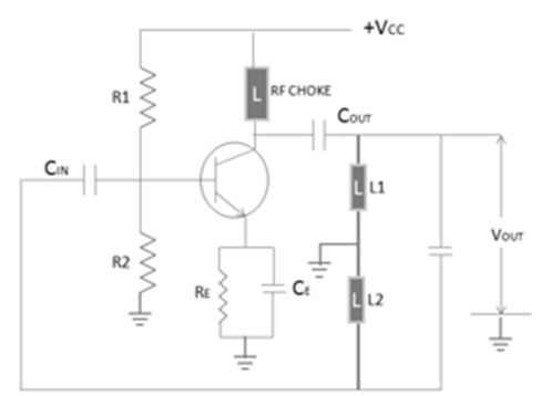
The Radio Frequency Choke (RFC) in the collector circuit acts as an open circuit at the RF frequency and prevents RF energy from entering the power supply. The tank circuit consists of L1, L2, and C. The frequency of oscillations is determined by the value of L1, L2, and C and is determined by the oscillates at the resonant frequency of the LC tank circuit. This resonant frequency is expressed as
$$f_o = \frac{1}{2\pi \sqrt{L_TC}}$$
The output signal can be taken from the collector by capacitive coupling, provided that the load is large and the frequency of oscillation is not affected.
Piezoelectricity
Piezoelectric properties are exhibited by a number of natural crystal substances, of which the most important are quartz, Rochelle salt, and tourmaline. When a sinusoidal voltage is applied across these materials, they vibrate at the applied voltage frequency.
On the other hand, when these materials are compressed and placed under mechanical strain to vibrate, they produce an equivalent sinusoidal voltage. Therefore, these materials are called as piezoelectric crystal. Quartz is the most popular piezoelectric crystal.
Crystal Oscillator
The circuit diagram of the crystal oscillator is shown in the following figure.
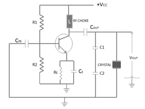
The crystal here acts as a tuned circuit. The equivalent circuit of a crystal is given below.
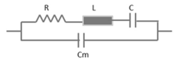
A crystal oscillator has two resonant frequencies: Series Resonant Frequency and Parallel Resonant Frequency.
Series Resonant Frequency
$$f_s = \frac{1}{2\pi \sqrt{LC}}$$
Parallel Resonant Frequency
$$f_p = \frac{1}{2\pi \sqrt{LC_T}}$$
The two resonant frequencies are almost same, since C/Cm is very small. In the above figure, the crystal is connected to operate in parallel resonant mode.
The resistors R1, R2, RE, and transistor together form an amplifier circuit. Resistors R1 and R2 provide a voltage stabilized DC bias. The capacitor (CE) provides AC bypass of the emitter resistor (RE) and the RFC provides high impedance to the frequency generated by the oscillator, so that they do not enter the power lines.
The crystal is in parallel with capacitor C1 and C2 and permits maximum voltage feedback from the collector to the emitter, when its impedance is maximum. At other frequencies, the crystal impedance is low and so the resultant feedback is too small to sustain oscillations. The oscillator frequency is stabilized at the parallel resonant frequency of the crystal.
