- Semiconductor Devices - Home
- Introduction
- Atomic Combinations
- Conduction in Solid Materials
- Conductivity & Mobility
- Types of Semiconductor
- Doping in Semiconductors
- Junction Diodes
- Depletion Zone
- Barrier Potential
- Junction Biasing
- Leakage Current
- Diode Characteristics
- Light Emitting Diode
- Zener Diode
- Photo Diode
- Photovoltaic Cells
- Varactor Diode
- Bipolar Transistors
- Construction of a Transistor
- Transistor Biasing
- Configuration of Transistors
- Field Effect Transistors
- JFET Biasing
- Semiconductor Devices - MOSFET
- Operational Amplifiers
- Practical Op-Amps
- Semiconductor Devices - Integrator
- Differentiator
- Oscillators
- Feedback & Compensation
- Semiconductor Devices - Quick Guide
- Semiconductor Devices - Resources
- Semiconductor Devices - Discussion
Semiconductor Devices - MOSFET
Metal-oxide semiconductor field-effect transistors, also known as MOSFETs, have greater importance and are a new addition to the FET family.
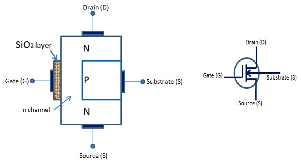
It has a lightly doped P type substrate into which two highly doped N type zones are diffused. A unique feature of this device is its gate construction. Here, the gate is completely insulated from the channel. When voltage is applied to the gate, it will develop an electrostatic charge.
At this point of time, no current is allowed to flow in the gate region of the device. Also, the gate is an area of the device, which is coated with metal. Generally, silicon dioxide is used as an insulating material between the gate and the channel. Due to this reason, it is also known as insulated gate FET. There are two MOSFETS widely used i) Depletion MOSFET ii) Enhancement MOSFET.
D MOSFET
The following figures show n-channel D-MOSFET and the symbol. The gate forms a capacitor with gate as one plate, and the other plate is the channel with SiO2 layer as dielectric. When the gate voltage varies, the electric field of the capacitor changes, which in turn varies the resistance of the n-channel.
In this case, we can either apply positive or negative voltage to the gate. When MOSFET is operated with negative gate voltage, it is called depletion mode and when operated with positive gate voltage it is called as enhancement mode of operation of MOSFET.
Depletion Mode
The following figure shows an n-channel D-MOSFET under depletion mode of operation.
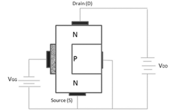
Its operation is as follows −
Most electrons are available on the gate as the gate is negative and it repels the electrons of n channel.
This action leaves positive ions in the part of the channel. In other words, some of the free electrons of the n channel are depleted. As a result, less number of electrons are available for current conduction through the n channel.
The greater the negative voltage at the gate, less is the current from the source to the drain. Thus, we can change the resistance of the n channel and the current from the source to the drain by varying the negative voltage on the gate.
Enhancement Mode
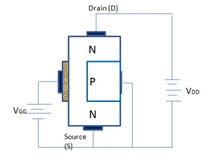
The following figure shows n channel D MOSFET under enhancement mode of operation. Here, the gate acts as a capacitor. However, in this case the gate is positive. It provokes the electrons in the n channel and the number of electrons increases in the n channel.
A positive gate voltage enhances or increases conductivity of the channel. The larger the positive voltage on the gate, greater the conduction from the source to the drain.
Thus, we can change the resistance of the n channel and the current from the source to the drain by varying the positive voltage on the gate.
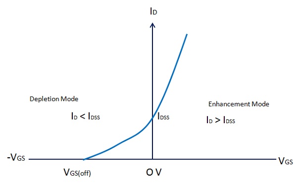
Transfer Characteristics of D MOSFET
The following figure shows transfer characteristics of D-MOSFET.
When VGS goes negative, ID falls below the value of IDSS, till it reaches zero and VGS = VGS (off) (Depletion mode). When VGS is zero, ID = IDSS because the gate and the source terminals are shorted. ID increases above the value of IDSS, when VGS is positive and the MOSFET is in enhancement mode.