
- Semiconductor Devices - Home
- Introduction
- Atomic Combinations
- Conduction in Solid Materials
- Conductivity & Mobility
- Types of Semiconductor
- Doping in Semiconductors
- Junction Diodes
- Depletion Zone
- Barrier Potential
- Junction Biasing
- Leakage Current
- Diode Characteristics
- Light Emitting Diode
- Zener Diode
- Photo Diode
- Photovoltaic Cells
- Varactor Diode
- Bipolar Transistors
- Construction of a Transistor
- Transistor Biasing
- Configuration of Transistors
- Field Effect Transistors
- JFET Biasing
- Semiconductor Devices - MOSFET
- Operational Amplifiers
- Practical Op-Amps
- Semiconductor Devices - Integrator
- Differentiator
- Oscillators
- Feedback & Compensation
- Semiconductor Devices - Quick Guide
- Semiconductor Devices - Resources
- Semiconductor Devices - Discussion
Configuration of Transistors
When a transistor is connected in a circuit, four terminals or leads or legs are required, two both for input and output. As we know that transistors have only 3 terminals, this situation can be overcome by making one of the terminal common for both input and output section. Accordingly, a transistor can be connected in three configurations as follows −
- Common Base Configuration
- Common Emitter Configuration
- Common Collector Configuration
Following are some important points to note about transistor operation.
A transistor can be operated in three regions namely active, saturation, and cutoff region.
A transistor when used in the active region, the base-emitter junction is forward biased and the collector-base junction is reverse biased.
A transistor when used in the saturation region, the base-emitter junction is forward biased and the collector-base junction is also forward biased.
A transistor when used in the cut-off region, both the base-emitter junction and collector-base junction are reverse biased.
Comparison of Transistor Configuration
The following table shows the comparison of transistor configuration.
| Characteristics | Common Emitter | Common Base | Common Collector |
|---|---|---|---|
| Current Gain | High | No | Considerable |
| Applications | Audio frequency | High frequency | Impedance matching |
| Input Resistance | Low | Low | Very high |
| Output Resistance | High | Very high | Low |
| Voltage Gain | Approx. 500 | Approx. 150 | Less than 1 |
Advantages and Disadvantages of Transistors
The following table lists the advantages and disadvantages of transistors.
| Advantages | Disadvantages |
|---|---|
| Low source voltage | Temperature dependency |
| High voltage gain | Lower power dissipation |
| Smaller in size | Low input impedance |
Current Amplification Factor (α)
The ratio of change in the collector current to the change in the emitter current at constant collector to base voltage Vcb is known as current amplification factor α. It can be expressed as
$\alpha = \frac{\Delta I_C}{\Delta I_B}$ at Constant VCB
It is clear that current amplification factor is less than unity and it is inversely proportional to the base current considered that the base is lightly doped and thin.
Base Current Amplification Factor (β)
It is the ratio of change in collector current to the change in base current. A small variation in base current results in a very large change in collector current. Therefore, the transistor is able to attain current gain. It can be expressed as
$$\beta = \frac{\Delta I_C}{\Delta I_B}$$
Transistor as an Amplifier
The following figure shows that a load resistor (RL) is in series with the collector supply voltage (Vcc). A small voltage change ΔVi between the emitter and the base causes a relatively large emitter-current change ΔIE.
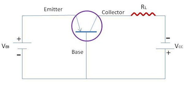
We define by the symbol a - the fraction of this current change - which is collected and passes through RL. The change in output voltage across the load resistor ΔVo = aRL ΔIE may be many times the change in input voltage ΔVI. Under these circumstances, the voltage amplification A == VO/ΔVI will be greater than unity and the transistor acts as an amplifier.
