
Article Categories
- All Categories
-
 Data Structure
-
 Networking
-
 RDBMS
RDBMS
-
 Operating System
-
 Java
Java
-
 MS Excel
-
 iOS
iOS
-
 HTML
HTML
-
 CSS
CSS
-
 Android
-
 Python
-
 C Programming
-
 C++
C++
-
 C#
C#
-
 MongoDB
-
 MySQL
MySQL
-
 Javascript
-
 PHP
PHP
-
 Economics & Finance
Programming the 8257
We know from the study of the description of 8257 that it consists of 40 pins and the condition when it works in Slave Mode and Master mode. From the microprocessor point of view, the I/O port is a chip which is used exclusively for DMA control application and is not used for interfacing I/O devices for the purpose of data transfer with the processor. This chip is only used to control the DMA data transfer for four I/O ports. For every I/O port there exists a corresponding DMA channel. This chip provides all the features which are needed for DMA data transfer. The concept of the Address Registers is given below.
Every DMA channel consists an address register and a count register. These registers are 16-bits wide in length. In each 16 bits there are four ARs marked as AR3-0. Apart from four CRs there are control and status registers also. They are separate 8-bit registers, but have the same address. Here the processor can only write in the control register but we can read in the status register.
We have four Counters, ranging from CR3-0, which consists of 16 bits each. At the time when the CR becomes access to the processor which is 16-bits wide, the Least Significant and the Most Significant Byte of the register are accessed in an alternate manner, which starts with the Least Significant Byte. Also, the M/L* flip-flop helps here. The information about the number of bytes which are to be transferred using DMA are contained in the Counter Registers, which is decremented by 1 for every byte in the DMA data transfer. When the Counter Register becomes 0, the last DMA data transfer results in activating the terminal count (TC) output by 8257. Among the four channels there is only one output reads The status port of 8257 are read by the processor to find out which channel is responsible for activating the output by the 8257.
The processor, in active state writes to the Control register of 8257 to configure its working purpose. To find out the status of 8257, the processor reads status register of the processor. The control register is of length 8-bits which is only read by the processor but not read. It is only selected when CS* is 0, A3-0 is 1000, and IOW* is 0.
The status register is of length 8-bits wide. The processor can only read but not write and it is only selected when CS* is 0, A3-0 is 1000, and IOR* is 0.
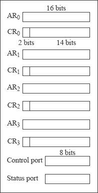
Fig. Programmer's view at a glance of Intel 8257.

505 Views
