
Article Categories
- All Categories
-
 Data Structure
-
 Networking
-
 RDBMS
RDBMS
-
 Operating System
-
 Java
Java
-
 MS Excel
-
 iOS
iOS
-
 HTML
HTML
-
 CSS
CSS
-
 Android
-
 Python
-
 C Programming
-
 C++
C++
-
 C#
C#
-
 MongoDB
-
 MySQL
MySQL
-
 Javascript
-
 PHP
PHP
-
 Economics & Finance
Programming the 8253
According to the microprocessor point of view, the 8253 is designed and has some specialty port chip I/O. We don't use it for interfering the I/O devices. For performing the application of time it is used. 8253 has the addressed A1 and A0 input pins.
The counters have width of 16 bits. If they were 8-bits wide, the delay in time that would be generated is very small. The Least Significant Byte and the Most Significant Byte of a counter is selected by using the same address of the port.
The processor here writes to the control port to configure the working of the three timers. Actually, here the processor writes to the control port to configure the three counters working.
The control port contains conveys the following information to 8253.
Selects configuration counter.
Configures the selected counters to perform a particular operation.
To decide selected counter is in decimal or in hexadecimal.
The counters can be configured to work in any of the following six modes of operation.
Mode0 − It interrupts in the terminal count;
Mode1 − re-triggerable input;
Mode2 − It generates rate;
Mode3 − It generates square wave;
Mode4 − It generates software trigger;
Mode5 − It generates hardware trigger.
For the discussion in this topic, the chip select circuit is assumed to be such that the port addresses are as follows.
| Address |
Port |
|---|---|
| 80H |
It is the counter 0 |
| 81H |
It is the counter 1 |
| 82H |
It is the counter 2 |
| 83H |
It is the Control port |
As a DIP package Intel 8253 is a 24-pin programmable IC available. IC has three counters which work independently and whose width is of 16-bits. In addition, we have a control port to decide what is the mode of working of the three counters. The physical and functional pin diagrams of them are indicated below.
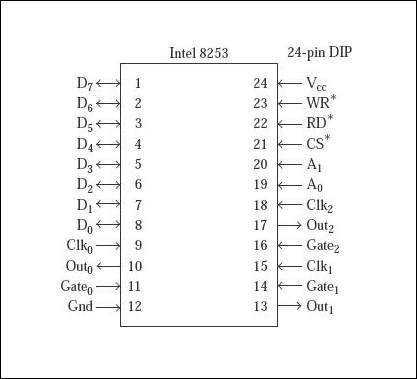
Fig.Diagram of 8253 pin based
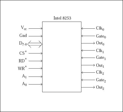
Fig.Pin diagram functional

676 Views
