
- Microprocessor - Home
- Microprocessor Overview
- Microprocessor Classification
- Microprocessor Evolution
- Microprocessor Components
- Microprocessor Characteristics
- Microprocessor Functions
- Microprocessor Pros & Cons
- Microprocessor Application
- Microcontrollers Types
- Microcontrollers Pros & Cons
- 8085 Microprocessor Architecture
- 8085 Microprocessor Pin Configuration
- Addressing Modes & Interrupts
- 8085 Microprocessor Instruction Sets
- 8085 Microprocessor Features
- Externally Initiated Operations
- 8086 Microprocessor
- 8086 Microprocessor Overview
- Functional Units
- Pin Configuration
- Instruction Sets
- 8086 Microprocessor Interrupts
- 8086 Microprocessor Addressing Modes
- 8086 Microprocessor Features
- Memory Segmentation
- Auxiliary Carry Flag
- Maximum and Minimum Mode Configurations
- Multiprocessor Configuration
- Configuration Overview
- 8087 Numeric Data Processor
- I/O Interfacing
- I/O Interfacing Overview
- 8279 Programmable Keyboard
- 8257 DMA Controller
- Serial vs Parallel Communication
- Serial Communications Interface
- Parallel Communication Interface
- 8051 Microcontrollers
- Microcontrollers Overview
- 8051 Microcontrollers Architecture
- 8051 Pin Description
- 8051 Input Output Ports
- 8051 Microcontrollers Interrupts
- Instruction Sets
- Logical Instructions in AVR
- Conditional Branch Instructions AVR
- Arithmetic Instructions in AVR
- External Memory Interfacing
- Time Delay in AVR
- 8051 vs PIC Microcontroller
- Peripheral Devices
- Peripheral Devices
- Programmable Peripheral Interface
- Intel 8255A Pin Description
- Programmable Interval Timer
- 8253/54 Operational Modes
- Interfacing Devices
- Applications and Furture Trends
- Microcontrollers - Application
- Microprocessors and Microcontrollers in IoT
- Microcontrollers in Automotive Systems
- Microcontrollers - Low-Power
- Artificial Intelligence Processors
- Microprocessor Useful Resources
- Microprocessor - Quick Guide
- Microprocessor - Useful Resources
- Microprocessor - Discussion
Microprocessor - 8257 DMA Controller
DMA stands for Direct Memory Access. It is designed by Intel to transfer data at the fastest rate. It allows the device to transfer the data directly to/from memory without any interference of the CPU.
Using a DMA controller, the device requests the CPU to hold its data, address and control bus, so the device is free to transfer data directly to/from the memory. The DMA data transfer is initiated only after receiving HLDA signal from the CPU.
How DMA Operations are Performed?
Following is the sequence of operations performed by a DMA −
Initially, when any device has to send data between the device and the memory, the device has to send DMA request (DRQ) to DMA controller.
The DMA controller sends Hold request (HRQ) to the CPU and waits for the CPU to assert the HLDA.
Then the microprocessor tri-states all the data bus, address bus, and control bus. The CPU leaves the control over bus and acknowledges the HOLD request through HLDA signal.
Now the CPU is in HOLD state and the DMA controller has to manage the operations over buses between the CPU, memory, and I/O devices.
Features of 8257
Here is a list of some of the prominent features of 8257 −
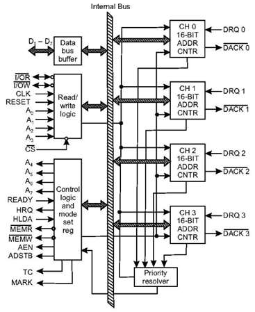
It has four channels which can be used over four I/O devices.
Each channel has 16-bit address and 14-bit counter.
Each channel can transfer data up to 64kb.
Each channel can be programmed independently.
Each channel can perform read transfer, write transfer and verify transfer operations.
It generates MARK signal to the peripheral device that 128 bytes have been transferred.
It requires a single phase clock.
Its frequency ranges from 250Hz to 3MHz.
It operates in 2 modes, i.e., Master mode and Slave mode.
8257 Architecture
The following image shows the architecture of 8257 −
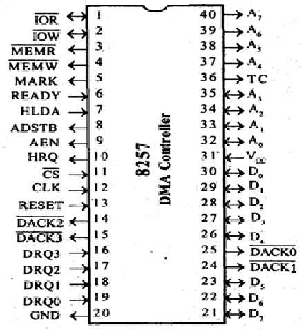
8257 Pin Description
The following image shows the pin diagram of a 8257 DMA controller −
DRQ0DRQ3
These are the four individual channel DMA request inputs, which are used by the peripheral devices for using DMA services. When the fixed priority mode is selected, then DRQ0 has the highest priority and DRQ3 has the lowest priority among them.
DACKo DACK3
These are the active-low DMA acknowledge lines, which updates the requesting peripheral about the status of their request by the CPU. These lines can also act as strobe lines for the requesting devices.
Do D7
These are bidirectional, data lines which are used to interface the system bus with the internal data bus of DMA controller. In the Slave mode, it carries command words to 8257 and status word from 8257. In the master mode, these lines are used to send higher byte of the generated address to the latch. This address is further latched using ADSTB signal.
IOR
It is an active-low bidirectional tri-state input line, which is used by the CPU to read internal registers of 8257 in the Slave mode. In the master mode, it is used to read data from the peripheral devices during a memory write cycle.
IOW
It is an active low bi-direction tri-state line, which is used to load the contents of the data bus to the 8-bit mode register or upper/lower byte of a 16-bit DMA address register or terminal count register. In the master mode, it is used to load the data to the peripheral devices during DMA memory read cycle.
CLK
It is a clock frequency signal which is required for the internal operation of 8257.
RESET
This signal is used to RESET the DMA controller by disabling all the DMA channels.
Ao - A3
These are the four least significant address lines. In the slave mode, they act as an input, which selects one of the registers to be read or written. In the master mode, they are the four least significant memory address output lines generated by 8257.
CS
It is an active-low chip select line. In the Slave mode, it enables the read/write operations to/from 8257. In the master mode, it disables the read/write operations to/from 8257.
A4 - A7
These are the higher nibble of the lower byte address generated by DMA in the master mode.
READY
It is an active-high asynchronous input signal, which makes DMA ready by inserting wait states.
HRQ
This signal is used to receive the hold request signal from the output device. In the slave mode, it is connected with a DRQ input line 8257. In Master mode, it is connected with HOLD input of the CPU.
HLDA
It is the hold acknowledgement signal which indicates the DMA controller that the bus has been granted to the requesting peripheral by the CPU when it is set to 1.
MEMR
It is the low memory read signal, which is used to read the data from the addressed memory locations during DMA read cycles.
MEMW
It is the active-low three state signal which is used to write the data to the addressed memory location during DMA write operation.
ADST
This signal is used to convert the higher byte of the memory address generated by the DMA controller into the latches.
AEN
This signal is used to disable the address bus/data bus.
TC
It stands for Terminal Count, which indicates the present DMA cycle to the present peripheral devices.
MARK
The mark will be activated after each 128 cycles or integral multiples of it from the beginning. It indicates the current DMA cycle is the 128th cycle since the previous MARK output to the selected peripheral device.
Vcc
It is the power signal which is required for the operation of the circuit.
