- Network Theory - Home
- Network Theory - Overview
- Example Problems
- Network Theory - Active Elements
- Network Theory - Passive Elements
- Network Theory - Kirchhoff’s Laws
- Electrical Quantity Division Principles
- Network Theory - Nodal Analysis
- Network Theory - Mesh Analysis
- Network Theory - Equivalent Circuits
- Equivalent Circuits Example Problem
- Delta to Star Conversion
- Star to Delta Conversion
- Network Theory - Network Topology
- Network Topology Matrices
- Superposition Theorem
- Thevenin’s Theorem
- Network Theory - Norton’s Theorem
- Maximum Power Transfer Theorem
- Response of DC Circuits
- Response of AC Circuits
- Network Theory - Series Resonance
- Parallel Resonance
- Network Theory - Coupled Circuits
- Two-Port Networks
- Two-Port Parameter Conversions
- Network Theory - Filters
Network Theory - Two-Port Networks
In general, it is easy to analyze any electrical network, if it is represented with an equivalent model, which gives the relation between input and output variables. For this, we can use two port network representations. As the name suggests, two port networks contain two ports. Among which, one port is used as an input port and the other port is used as an output port. The first and second ports are called as port1 and port2 respectively.
One port network is a two terminal electrical network in which, current enters through one terminal and leaves through another terminal. Resistors, inductors and capacitors are the examples of one port network because each one has two terminals. One port network representation is shown in the following figure.
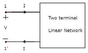
Here, the pair of terminals, 1 & 1 represents a port. In this case, we are having only one port since it is a one port network.
Similarly, two port network is a pair of two terminal electrical network in which, current enters through one terminal and leaves through another terminal of each port. Two port network representation is shown in the following figure.
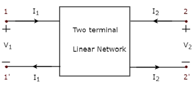
Here, one pair of terminals, 1 & 1 represents one port, which is called as port1 and the other pair of terminals, 2 & 2 represents another port, which is called as port2.
There are four variables V1, V2, I1 and I2 in a two port network as shown in the figure. Out of which, we can choose two variables as independent and another two variables as dependent. So, we will get six possible pairs of equations. These equations represent the dependent variables in terms of independent variables. The coefficients of independent variables are called as parameters. So, each pair of equations will give a set of four parameters.
Two Port Network Parameters
The parameters of a two port network are called as two port network parameters or simply, two port parameters. Following are the types of two port network parameters.
- Z parameters
- Y parameters
- T parameters
- T parameters
- h-parameters
- g-parameters
Now, let us discuss about these two port network parameters one by one.
Z parameters
We will get the following set of two equations by considering the variables V1 & V2 as dependent and I1 & I2 as independent. The coefficients of independent variables, I1 and I2 are called as Z parameters.
$$V_1 = Z_{11} I_1 + Z_{12} I_2$$
$$V_2 = Z_{21} I_1 + Z_{22} I_2$$
The Z parameters are
$$Z_{11} = \frac{V_1}{I_1}, \: when \: I_2 = 0$$
$$Z_{12} = \frac{V_1}{I_2}, \: when \: I_1 = 0$$
$$Z_{21} = \frac{V_2}{I_1}, \: when \: I_2 = 0$$
$$Z_{22} = \frac{V_2}{I_2}, \: when \: I_1 = 0$$
Z parameters are called as impedance parameters because these are simply the ratios of voltages and currents. Units of Z parameters are Ohm (Ω).
We can calculate two Z parameters, Z11 and Z21, by doing open circuit of port2. Similarly, we can calculate the other two Z parameters, Z12 and Z22 by doing open circuit of port1. Hence, the Z parameters are also called as open-circuit impedance parameters.
Y parameters
We will get the following set of two equations by considering the variables I1 & I2 as dependent and V1 & V2 as independent. The coefficients of independent variables, V1 and V2 are called as Y parameters.
$$I_1 = Y_{11} V_1 + Y_{12} V_2$$
$$I_2 = Y_{21} V_1 + Y_{22} V_2$$
The Y parameters are
$$Y_{11} = \frac{I_1}{V_1}, \: when \: V_2 = 0$$
$$Y_{12} = \frac{I_1}{V_2}, \: when \: V_1 = 0$$
$$Y_{21} = \frac{I_2}{V_1}, \: when \: V_2 = 0$$
$$Y_{22} = \frac{I_2}{V_2}, \: when \: V_1 = 0$$
Y parameters are called as admittance parameters because these are simply, the ratios of currents and voltages. Units of Y parameters are mho.
We can calculate two Y parameters, Y11 and Y21 by doing short circuit of port2. Similarly, we can calculate the other two Y parameters, Y12 and Y22 by doing short circuit of port1. Hence, the Y parameters are also called as short-circuit admittance parameters.
T parameters
We will get the following set of two equations by considering the variables V1 & I1 as dependent and V2 & I2 as independent. The coefficients of V2 and -I2 are called as T parameters.
$$V_1 = A V_2 - B I_2$$
$$I_1 = C V_2 - D I_2$$
The T parameters are
$$A = \frac{V_1}{V_2}, \: when \: I_2 = 0$$
$$B = -\frac{V_1}{I_2}, \: when \: V_2 = 0$$
$$C = \frac{I_1}{V_2}, \: when \: I_2 = 0$$
$$D = -\frac{I_1}{I_2}, \: when \: V_2 = 0$$
T parameters are called as transmission parameters or ABCD parameters. The parameters, A and D do not have any units, since those are dimension less. The units of parameters, B and C are ohm and mho respectively.
We can calculate two parameters, A and C by doing open circuit of port2. Similarly, we can calculate the other two parameters, B and D by doing short circuit of port2.
T parameters
We will get the following set of two equations by considering the variables V2 & I2 as dependent and V1 & I1 as independent. The coefficients of V1 and -I1 are called as T parameters.
$$V_2 = A' V_1 - B' I_1$$
$$I_2 = C' V_1 - D' I_1$$
The T parameters are
$$A' = \frac{V_2}{V_1}, \: when\: I_1 = 0$$
$$B' = -\frac{V_2}{I_1}, \: when\: V_1 = 0$$
$$C' = \frac{I_2}{V_1}, \: when\: I_1 = 0$$
$$D' = -\frac{I_2}{I_1}, \: when \: V_1 = 0$$
T parameters are called as inverse transmission parameters or ABCD parameters. The parameters A and D do not have any units, since those are dimension less. The units of parameters, B and C, are Ohm and Mho respectively.
We can calculate two parameters, A and C, by doing an open circuit of port1. Similarly, we can calculate the other two parameters, B and D, by doing a short circuit of port1.
h-parameters
We will get the following set of two equations by considering the variables V1 & I2 as dependent and I1 & V2 as independent. The coefficients of independent variables, I1 and V2, are called as h-parameters.
$$V_1 = h_{11} I_1 + h_{12} V_2$$
$$I_2 = h_{21} I_1 + h_{22} V_2$$
The h-parameters are
$$h_{11} = \frac{V_1}{I_1},\: when\: V_2 = 0$$
$$h_{12} = \frac{V_1}{V_2},\: when\: I_1 = 0$$
$$h_{21} = \frac{I_2}{I_1},\: when\: V_2 = 0$$
$$h_{22} = \frac{I_2}{V_2},\: when\: I_1 = 0$$
h-parameters are called as hybrid parameters. The parameters, h12 and h21, do not have any units, since those are dimension-less. The units of parameters, h11 and h22, are Ohm and Mho respectively.
We can calculate two parameters, h11 and h21 by doing short circuit of port2. Similarly, we can calculate the other two parameters, h12 and h22 by doing open circuit of port1.
The h-parameters or hybrid parameters are useful in transistor modelling circuits (networks).
g-parameters
We will get the following set of two equations by considering the variables I1 & V2 as dependent and V1 & I2 as independent. The coefficients of independent variables, V1 and I2 are called as g-parameters.
$$I_1 = g_{11} V_1 + g_{12} I_2$$
$$V_2 = g_{21} V_1 + g_{22} I_2$$
The g-parameters are
$$g_{11} = \frac{I_1}{V_1},\: when\: I_2 = 0$$
$$g_{12} = \frac{I_1}{I_2},\: when\: V_1 = 0$$
$$g_{21} = \frac{V_2}{V_1},\: when\: I_2 = 0$$
$$g_{22} = \frac{V_2}{I_2},\: when \: V_1 = 0$$
g-parameters are called as inverse hybrid parameters. The parameters, g12 and g21 do not have any units, since those are dimension less. The units of parameters, g11 and g22 are mho and ohm respectively.
We can calculate two parameters, g11 and g21 by doing open circuit of port2. Similarly, we can calculate the other two parameters, g12 and g22 by doing short circuit of port1.
