- Network Theory - Home
- Network Theory - Overview
- Example Problems
- Network Theory - Active Elements
- Network Theory - Passive Elements
- Network Theory - Kirchhoff’s Laws
- Electrical Quantity Division Principles
- Network Theory - Nodal Analysis
- Network Theory - Mesh Analysis
- Network Theory - Equivalent Circuits
- Equivalent Circuits Example Problem
- Delta to Star Conversion
- Star to Delta Conversion
- Network Theory - Network Topology
- Network Topology Matrices
- Superposition Theorem
- Thevenin’s Theorem
- Network Theory - Norton’s Theorem
- Maximum Power Transfer Theorem
- Response of DC Circuits
- Response of AC Circuits
- Network Theory - Series Resonance
- Parallel Resonance
- Network Theory - Coupled Circuits
- Two-Port Networks
- Two-Port Parameter Conversions
- Network Theory - Filters
Network Theory - Series Resonance
Resonance occurs in electric circuits due to the presence of energy storing elements like inductor and capacitor. It is the fundamental concept based on which, the radio and TV receivers are designed in such a way that they should be able to select only the desired station frequency.
There are two types of resonances, namely series resonance and parallel resonance. These are classified based on the network elements that are connected in series or parallel. In this chapter, let us discuss about series resonance.
Series Resonance Circuit Diagram
If the resonance occurs in series RLC circuit, then it is called as Series Resonance. Consider the following series RLC circuit, which is represented in phasor domain.
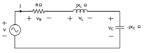
Here, the passive elements such as resistor, inductor and capacitor are connected in series. This entire combination is in series with the input sinusoidal voltage source.
Apply KVL around the loop.
$$V - V_R - V_L - V_C = 0$$
$$\Rightarrow V - IR - I(j X_L) - I(-j X_C) = 0$$
$$\Rightarrow V = IR + I(j X_L) + I(-j X_C)$$
$\Rightarrow V = I[R + j(X_L - X_C)]$Equation 1
The above equation is in the form of V = IZ.
Therefore, the impedance Z of series RLC circuit will be
$$Z = R + j(X_L - X_C)$$
Parameters & Electrical Quantities at Resonance
Now, let us derive the values of parameters and electrical quantities at resonance of series RLC circuit one by one.
Resonant Frequency
The frequency at which resonance occurs is called as resonant frequency fr. In series RLC circuit resonance occurs, when the imaginary term of impedance Z is zero, i.e., the value of $X_L - X_C$ should be equal to zero.
$$\Rightarrow X_L = X_C$$
Substitute $X_L = 2 \pi f L$ and $X_C = \frac{1}{2 \pi f C}$ in the above equation.
$$2 \pi f L = \frac{1}{2 \pi f C}$$
$$\Rightarrow f^2 = \frac{1}{(2 \pi)^2 L C}$$
$$\Rightarrow f = \frac{1}{(2 \pi) \sqrt{LC}}$$
Therefore, the resonant frequency fr of series RLC circuit is
$$f_r = \frac{1}{(2 \pi) \sqrt{LC}}$$
Where, L is the inductance of an inductor and C is the capacitance of a capacitor.
The resonant frequency fr of series RLC circuit depends only on the inductance L and capacitance C. But, it is independent of resistance R.
Impedance
We got the impedance Z of series RLC circuit as
$$Z = R + j(X_L - X_C)$$
Substitute $X_L = X_C$ in the above equation.
$$Z = R + j(X_C - X_C)$$
$$\Rightarrow Z = R + j(0)$$
$$\Rightarrow Z = R$$
At resonance, the impedance Z of series RLC circuit is equal to the value of resistance R, i.e., Z = R.
Current flowing through the Circuit
Substitute $X_L - X_C = 0$ in Equation 1.
$$V = I[R + j(0)]$$
$$\Rightarrow V = IR$$
$$\Rightarrow I = \frac{V}{R}$$
Therefore, current flowing through series RLC circuit at resonance is $\mathbf{\mathit{I = \frac{V}{R}}}$.
At resonance, the impedance of series RLC circuit reaches to minimum value. Hence, the maximum current flows through this circuit at resonance.
Voltage across Resistor
The voltage across resistor is
$$V_R = IR$$
Substitute the value of I in the above equation.
$$V_R = \lgroup \frac{V}{R} \rgroup R$$
$$\Rightarrow V_R = V$$
Therefore, the voltage across resistor at resonance is VR = V.
Voltage across Inductor
The voltage across inductor is
$$V_L = I(jX_L)$$
Substitute the value of I in the above equation.
$$V_L = \lgroup \frac{V}{R} \rgroup (jX_L)$$
$$\Rightarrow V_L = j \lgroup \frac{X_L}{R} \rgroup V$$
$$\Rightarrow V_L = j QV$$
Therefore, the voltage across inductor at resonance is $V_L = j QV$.
So, the magnitude of voltage across inductor at resonance will be
$$|V_L| = QV$$
Where Q is the Quality factor and its value is equal to $\frac{X_L}{R}$
Voltage across Capacitor
The voltage across capacitor is
$$V_C = I(-j X_C)$$
Substitute the value of I in the above equation.
$$V_C = \lgroup \frac{V}{R} \rgroup (-j X_C)$$
$$\Rightarrow V_C = -j \lgroup \frac{X_C}{R} \rgroup V$$
$$\Rightarrow V_C = -jQV$$
Therefore, the voltage across capacitor at resonance is $\mathbf{\mathit{V_C = -jQV}}$.
So, the magnitude of voltage across capacitor at resonance will be
$$|V_C| = QV$$
Where Q is the Quality factor and its value is equal to $\frac{X_{C}}{R}$
Note − Series resonance RLC circuit is called as voltage magnification circuit, because the magnitude of voltage across the inductor and the capacitor is equal to Q times the input sinusoidal voltage V.
