- Network Theory - Home
- Network Theory - Overview
- Example Problems
- Network Theory - Active Elements
- Network Theory - Passive Elements
- Network Theory - Kirchhoff’s Laws
- Electrical Quantity Division Principles
- Network Theory - Nodal Analysis
- Network Theory - Mesh Analysis
- Network Theory - Equivalent Circuits
- Equivalent Circuits Example Problem
- Delta to Star Conversion
- Star to Delta Conversion
- Network Theory - Network Topology
- Network Topology Matrices
- Superposition Theorem
- Thevenin’s Theorem
- Network Theory - Norton’s Theorem
- Maximum Power Transfer Theorem
- Response of DC Circuits
- Response of AC Circuits
- Network Theory - Series Resonance
- Parallel Resonance
- Network Theory - Coupled Circuits
- Two-Port Networks
- Two-Port Parameter Conversions
- Network Theory - Filters
Network Theory - Passive Elements
In this chapter, we will discuss in detail about the passive elements such as Resistor, Inductor, and Capacitor. Let us start with Resistors.
Resistor
The main functionality of Resistor is either opposes or restricts the flow of electric current. Hence, the resistors are used in order to limit the amount of current flow and / or dividing (sharing) voltage.
Let the current flowing through the resistor is I amperes and the voltage across it is V volts. The symbol of resistor along with current, I and voltage, V are shown in the following figure.
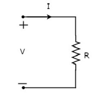
According to Ohms law, the voltage across resistor is the product of current flowing through it and the resistance of that resistor. Mathematically, it can be represented as
$V = IR$ Equation 1
$\Rightarrow I = \frac{V}{R}$Equation 2
Where, R is the resistance of a resistor.
From Equation 2, we can conclude that the current flowing through the resistor is directly proportional to the applied voltage across resistor and inversely proportional to the resistance of resistor.
Power in an electric circuit element can be represented as
$P = VI$Equation 3
Substitute, Equation 1 in Equation 3.
$P = (IR)I$
$\Rightarrow P = I^2 R$ Equation 4
Substitute, Equation 2 in Equation 3.
$P = V \lgroup \frac{V}{R} \rgroup$
$\Rightarrow P = \frac{V^2}{R}$ Equation 5
So, we can calculate the amount of power dissipated in the resistor by using one of the formulae mentioned in Equations 3 to 5.
Inductor
In general, inductors will have number of turns. Hence, they produce magnetic flux when current flows through it. So, the amount of total magnetic flux produced by an inductor depends on the current, I flowing through it and they have linear relationship.
Mathematically, it can be written as
$$\Psi \: \alpha \: I$$
$$\Rightarrow \Psi = LI$$
Where,
Ψ is the total magnetic flux
L is the inductance of an inductor
Let the current flowing through the inductor is I amperes and the voltage across it is V volts. The symbol of inductor along with current I and voltage V are shown in the following figure.
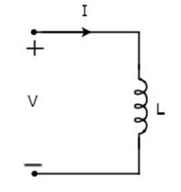
According to Faradays law, the voltage across the inductor can be written as
$$V = \frac{d\Psi}{dt}$$
Substitute Ψ = LI in the above equation.
$$V = \frac{d(LI)}{dt}$$
$$\Rightarrow V = L \frac{dI}{dt}$$
$$\Rightarrow I = \frac{1}{L} \int V dt$$
From the above equations, we can conclude that there exists a linear relationship between voltage across inductor and current flowing through it.
We know that power in an electric circuit element can be represented as
$$P = VI$$
Substitute $V = L \frac{dI}{dt}$ in the above equation.
$$P = \lgroup L \frac{dI}{dt}\rgroup I$$
$$\Rightarrow P = LI \frac{dI}{dt}$$
By integrating the above equation, we will get the energy stored in an inductor as
$$W = \frac{1}{2} LI^2$$
So, the inductor stores the energy in the form of magnetic field.
Capacitor
In general, a capacitor has two conducting plates, separated by a dielectric medium. If positive voltage is applied across the capacitor, then it stores positive charge. Similarly, if negative voltage is applied across the capacitor, then it stores negative charge.
So, the amount of charge stored in the capacitor depends on the applied voltage V across it and they have linear relationship. Mathematically, it can be written as
$$Q \: \alpha \: V$$
$$\Rightarrow Q = CV$$
Where,
Q is the charge stored in the capacitor.
C is the capacitance of a capacitor.
Let the current flowing through the capacitor is I amperes and the voltage across it is V volts. The symbol of capacitor along with current I and voltage V are shown in the following figure.
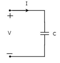
We know that the current is nothing but the time rate of flow of charge. Mathematically, it can be represented as
$$I = \frac{dQ}{dt}$$
Substitute $Q = CV$ in the above equation.
$$I = \frac{d(CV)}{dt}$$
$$\Rightarrow I = C \frac{dV}{dt}$$
$$\Rightarrow V = \frac{1}{C} \int I dt$$
From the above equations, we can conclude that there exists a linear relationship between voltage across capacitor and current flowing through it.
We know that power in an electric circuit element can be represented as
$$P = VI$$
Substitute $I = C \frac{dV}{dt}$ in the above equation.
$$P = V \lgroup C \frac{dV}{dt} \rgroup$$
$$\Rightarrow P = CV \frac{dV}{dt}$$
By integrating the above equation, we will get the energy stored in the capacitor as
$$W = \frac{1}{2}CV^2$$
So, the capacitor stores the energy in the form of electric field.
