- Network Theory - Home
- Network Theory - Overview
- Example Problems
- Network Theory - Active Elements
- Network Theory - Passive Elements
- Network Theory - Kirchhoff’s Laws
- Electrical Quantity Division Principles
- Network Theory - Nodal Analysis
- Network Theory - Mesh Analysis
- Network Theory - Equivalent Circuits
- Equivalent Circuits Example Problem
- Delta to Star Conversion
- Star to Delta Conversion
- Network Theory - Network Topology
- Network Topology Matrices
- Superposition Theorem
- Thevenin’s Theorem
- Network Theory - Norton’s Theorem
- Maximum Power Transfer Theorem
- Response of DC Circuits
- Response of AC Circuits
- Network Theory - Series Resonance
- Parallel Resonance
- Network Theory - Coupled Circuits
- Two-Port Networks
- Two-Port Parameter Conversions
- Network Theory - Filters
Network Theory - Filters
Filters as the name suggests, they filter the frequency components. That means, they allow certain frequency components and / or reject some other frequency components.
In this chapter, let us discuss about the passive filters. Those are the electric circuits or networks having passive elements like resistor, inductor and capacitor.
Types of Filters
Filters are mainly classified into four types based on the band of frequencies that are allowing and / or the band of frequencies that are rejecting. Following are the types of filters.
- Low Pass Filter
- High Pass Filter
- Band Pass Filter
- Band Stop Filter
Low Pass Filter
Low pass filter as the name suggests, it allows (passes) only low frequency components. That means, it rejects (blocks) all other high frequency components.
The s-domain circuit diagram (network) of Low Pass Filter is shown in the following figure.
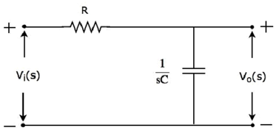
It consists of two passive elements resistor and capacitor, which are connected in series. Input voltage is applied across this entire combination and the output is considered as the voltage across capacitor.
Here, $V_i(s)$ and $V_o(s)$ are the Laplace transforms of input voltage, $v_i(t)$ and output voltage, $v_o(t)$ respectively.
The transfer function of the above network is
$$H(s) = \frac{V_o(s)}{V_i(s)} = \frac{\frac{1}{sC}}{R + \frac{1}{sC}}$$
$$\Rightarrow H(s) = \frac{1}{1 + sCR}$$
Substitute, $s = j \omega$ in the above equation.
$$H(j \omega) = \frac{1}{1 + j \omega CR}$$
Magnitude of transfer function is
$$|H(j \omega)| = \frac{1}{\sqrt{(1 + (\omega CR)^2}}$$
At ω = 0, the magnitude of transfer function is equal to 1.
At $\omega = \frac{1}{CR}$, the magnitude of transfer function is equal to 0.707.
At ω = ∞, the magnitude of transfer function is equal to 0.
Therefore, the magnitude of transfer function of Low pass filter will vary from 1 to 0 as ω varies from 0 to ∞.
High Pass Filter
High pass filter as the name suggests, it allows (passes) only high frequency components. That means, it rejects (blocks) all low frequency components.
The s-domain circuit diagram (network) of High pass filter is shown in the following figure.
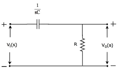
It consists of two passive elements capacitor and resistor, which are connected in series. Input voltage is applied across this entire combination and the output is considered as the voltage across resistor.
Here, $V_i(s)$ and $V_o(s)$ are the Laplace transforms of input voltage, $v_i(t)$ and output voltage, $v_o(t)$ respectively.
The transfer function of the above network is
$$H(s) = \frac{V_o(s)}{V_i(s)} = \frac{R}{R + \frac{1}{sC}}$$
$$\Rightarrow H(s) = \frac{sCR}{1 + sCR}$$
Substitute, $s = j \omega$ in the above equation.
$$H(j \omega) = \frac{j \omega CR}{1 + j \omega CR}$$
Magnitude of transfer function is
$$|H(j \omega)| = \frac{\omega CR}{\sqrt{(1 + (\omega CR)^2}}$$
At ω = 0, the magnitude of transfer function is equal to 0.
At $\omega = \frac{1}{CR}$, the magnitude of transfer function is equal to 0.707.
At ω = ∞, the magnitude of transfer function is equal to 1.
Therefore, the magnitude of transfer function of High pass filter will vary from 0 to 1 as ω varies from 0 to ∞.
Band Pass Filter
Band pass filter as the name suggests, it allows (passes) only one band of frequencies. In general, this frequency band lies in between low frequency range and high frequency range. That means, this filter rejects (blocks) both low and high frequency components.
The s-domain circuit diagram (network) of Band pass filter is shown in the following figure.
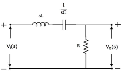
It consists of three passive elements inductor, capacitor and resistor, which are connected in series. Input voltage is applied across this entire combination and the output is considered as the voltage across resistor.
Here, $V_i(s)$ and $V_o(s)$ are the Laplace transforms of input voltage, $v_i(t)$ and output voltage, $v_o(t)$ respectively.
The transfer function of the above network is
$$H(s) = \frac{V_o(s)}{V_i(s)} = \frac{R}{R + \frac{1}{sC} + sL}$$
$$\Rightarrow H(s) = \frac{s CR}{s^2 LC + sCR + 1}$$
Substitute $s = j \omega$ in the above equation.
$$H(j \omega) = \frac{j \omega CR}{1 - \omega^2 LC + j \omega CR}$$
Magnitude of transfer function is
$$|H(j \omega)| = \frac{\omega CR}{\sqrt{(1 - \omega^2 LC)^2 + (\omega CR)^2}}$$
At ω = 0, the magnitude of transfer function is equal to 0.
At $\omega = \frac{1}{\sqrt{LC}}$, the magnitude of transfer function is equal to 1.
At ω = ∞, the magnitude of transfer function is equal to 0.
Therefore, the magnitude of transfer function of Band pass filter will vary from 0 to 1 & 1 to 0 as ω varies from 0 to ∞.
Band Stop Filter
Band stop filter as the name suggests, it rejects (blocks) only one band of frequencies. In general, this frequency band lies in between low frequency range and high frequency range. That means, this filter allows (passes) both low and high frequency components.
The s-domain (network) of circuit diagramand stop filter is shown in the following figure.
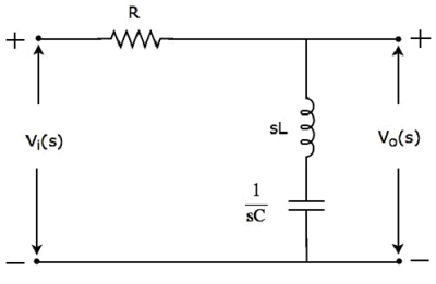
It consists of three passive elements resistor, inductor and capacitor, which are connected in series. Input voltage is applied across this entire combination and the output is considered as the voltage across the combination of inductor and capacitor.
Here, $V_i(s)$ and $V_o(s)$ are the Laplace transforms of input voltage, $v_i(t)$ and output voltage, $v_o(t)$ respectively.
The transfer function of the above network is
$$H(s) = \frac{V_o(s)}{V_i(s)} = \frac{sL + \frac{1}{sC}}{R + sL + \frac{1}{sC}}$$
$$\Rightarrow H(s) = \frac{s^2 LC + 1}{s^2 LC + sCR + 1}$$
Substitute, $s = j \omega$ in the above equation.
$$H(j \omega) = \frac{1 - \omega^2 LC}{1 - \omega^2 LC + j \omega CR}$$
Magnitude of transfer function is
$$|H(j \omega)| = \frac{1 - \omega^2 LC}{\sqrt{(1 - \omega^2 LC)^2 + (\omega CR)^2}}$$
At ω = 0, the magnitude of transfer function is equal to 1.
At $\omega = \frac{1}{\sqrt{LC}}$, the magnitude of transfer function is equal to 0.
At ω = ∞, the magnitude of transfer function is equal to 1.
Therefore, the magnitude of transfer function of Band stop filter will vary from 1 to 0 & 0 to 1 as ω varies from 0 to ∞.
