- Network Theory - Home
- Network Theory - Overview
- Example Problems
- Network Theory - Active Elements
- Network Theory - Passive Elements
- Network Theory - Kirchhoff’s Laws
- Electrical Quantity Division Principles
- Network Theory - Nodal Analysis
- Network Theory - Mesh Analysis
- Network Theory - Equivalent Circuits
- Equivalent Circuits Example Problem
- Delta to Star Conversion
- Star to Delta Conversion
- Network Theory - Network Topology
- Network Topology Matrices
- Superposition Theorem
- Thevenin’s Theorem
- Network Theory - Norton’s Theorem
- Maximum Power Transfer Theorem
- Response of DC Circuits
- Response of AC Circuits
- Network Theory - Series Resonance
- Parallel Resonance
- Network Theory - Coupled Circuits
- Two-Port Networks
- Two-Port Parameter Conversions
- Network Theory - Filters
Network Theory - Nodal Analysis
There are two basic methods that are used for solving any electrical network: Nodal analysis and Mesh analysis. In this chapter, let us discuss about the Nodal analysis method.
In Nodal analysis, we will consider the node voltages with respect to Ground. Hence, Nodal analysis is also called as Node-voltage method.
Procedure of Nodal Analysis
Follow these steps while solving any electrical network or circuit using Nodal analysis.
Step 1 − Identify the principal nodes and choose one of them as reference node. We will treat that reference node as the Ground.
Step 2 − Label the node voltages with respect to Ground from all the principal nodes except the reference node.
Step 3 − Write nodal equations at all the principal nodes except the reference node. Nodal equation is obtained by applying KCL first and then Ohms law.
Step 4 − Solve the nodal equations obtained in Step 3 in order to get the node voltages.
Now, we can find the current flowing through any element and the voltage across any element that is present in the given network by using node voltages.
Example
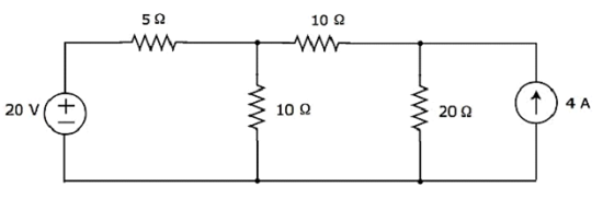
Find the current flowing through 20 Ω resistor of the following circuit using Nodal analysis.
Step 1 − There are three principle nodes in the above circuit. Those are labelled as 1, 2, and 3 in the following figure.
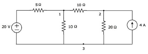
In the above figure, consider node 3 as reference node (Ground).
Step 2 − The node voltages, V1 and V2, are labelled in the following figure.
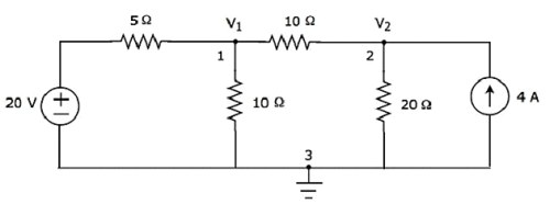
In the above figure, V1 is the voltage from node 1 with respect to ground and V2 is the voltage from node 2 with respect to ground.
Step 3 − In this case, we will get two nodal equations, since there are two principal nodes, 1 and 2, other than Ground. When we write the nodal equations at a node, assume all the currents are leaving from the node for which the direction of current is not mentioned and that nodes voltage as greater than other node voltages in the circuit.
The nodal equation at node 1 is
$$\frac{V_1 - 20}{5} + \frac{V_1}{10} + \frac{V_1 - V_2}{10} = 0$$
$$\Rightarrow \frac{2 V_1 - 40 + V_1 + V_1 - V_2}{10} = 0$$
$$\Rightarrow 4V_1 - 40 - V_2 = 0$$
$\Rightarrow V_2 = 4V_1 - 40$ Equation 1
The nodal equation at node 2 is
$$-4 + \frac{V_2}{20} + \frac{V_2 - V_1}{10} = 0$$
$$\Rightarrow \frac{-80 + V_2 + 2V_2 - 2V_2}{20} = 0$$
$\Rightarrow 3V_2 2V_1 = 80$ Equation 2
Step 4 − Finding node voltages, V1 and V2 by solving Equation 1 and Equation 2.
Substitute Equation 1 in Equation 2.
$$3(4 V_1 - 40) - 2 V_1 = 80$$
$$\Rightarrow 12 V_1 - 120 - 2V_1 =80$$
$$\Rightarrow 10 V_1 = 200$$
$$\Rightarrow V_1 = 20V$$
Substitute V1 = 20 V in Equation1.
$$V_2 = 4(20) - 40$$
$$\Rightarrow V_2 = 40V$$
So, we got the node voltages V1 and V2 as 20 V and 40 V respectively.
Step 5 − The voltage across 20 Ω resistor is nothing but the node voltage V2 and it is equal to 40 V. Now, we can find the current flowing through 20 Ω resistor by using Ohms law.
$$I_{20 \Omega} = \frac{V_2}{R}$$
Substitute the values of V2 and R in the above equation.
$$I_{20 \Omega} = \frac{40}{20}$$
$$\Rightarrow I_{20 \Omega} = 2A$$
Therefore, the current flowing through 20 Ω resistor of given circuit is 2 A.
Note − From the above example, we can conclude that we have to solve n nodal equations, if the electric circuit has n principal nodes (except the reference node). Therefore, we can choose Nodal analysis when the number of principal nodes (except reference node) is less than the number of meshes of any electrical circuit.
