- Network Theory - Home
- Network Theory - Overview
- Example Problems
- Network Theory - Active Elements
- Network Theory - Passive Elements
- Network Theory - Kirchhoff’s Laws
- Electrical Quantity Division Principles
- Network Theory - Nodal Analysis
- Network Theory - Mesh Analysis
- Network Theory - Equivalent Circuits
- Equivalent Circuits Example Problem
- Delta to Star Conversion
- Star to Delta Conversion
- Network Theory - Network Topology
- Network Topology Matrices
- Superposition Theorem
- Thevenin’s Theorem
- Network Theory - Norton’s Theorem
- Maximum Power Transfer Theorem
- Response of DC Circuits
- Response of AC Circuits
- Network Theory - Series Resonance
- Parallel Resonance
- Network Theory - Coupled Circuits
- Two-Port Networks
- Two-Port Parameter Conversions
- Network Theory - Filters
Network Theory - Response of AC Circuits
In the previous chapter, we discussed the transient response and steady state response of DC circuit. In this chapter, let us discuss the response of AC circuit. The concepts of both transient response and steady state response, which we discussed in the previous chapter, will be useful here too.
Finding the Response of Series RL Circuit
Consider the following series RL circuit diagram.
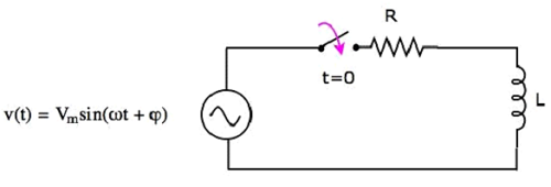
In the above circuit, the switch was kept open up to t = 0 and it was closed at t = 0. So, the AC voltage source having a peak voltage of Vm volts is not connected to the series RL circuit up to this instant. Therefore, there is no initial current flows through the inductor.
The circuit diagram, when the switch is in closed position, is shown in the following figure.
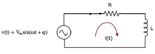
Now, the current i(t) flows in the entire circuit, since the AC voltage source having a peak voltage of Vm volts is connected to the series RL circuit.
We know that the current i(t) flowing through the above circuit will have two terms, one that represents the transient part and other term represents the steady state.
Mathematically, it can be represented as
$i(t) = i_{Tr}(t) + i_{ss}(t)$Equation 1
Where,
$i_{Tr}(t)$ is the transient response of the current flowing through the circuit.
$i_{ss}(t)$ is the steady state response of the current flowing through the circuit.
In the previous chapter, we got the transient response of the current flowing through the series RL circuit. It is in the form of $Ke^{-\lgroup \frac{t}{\tau} \rgroup}$.
Substitute $i_{Tr}(t) = Ke^{-\lgroup \frac{t}{\tau} \rgroup}$ in Equation 1.
$i(t) = Ke^{-\lgroup \frac{t}{\tau} \rgroup} + i_{ss}(t)$Equation 2
Calculation of Steady State Current
If a sinusoidal signal is applied as an input to a Linear electric circuit, then it produces a steady state output, which is also a sinusoidal signal. Both the input and output sinusoidal signals will be having the same frequency, but different amplitudes and phase angles.
We can calculate the steady state response of an electric circuit, when it is excited by a sinusoidal voltage source using Laplace Transform approach.
The s-domain circuit diagram, when the switch is in closed position, is shown in the following figure.
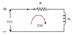
In the above circuit, all the quantities and parameters are represented in s-domain. These are the Laplace transforms of time-domain quantities and parameters.
The Transfer function of the above circuit is
$$H(s) = \frac{I(s)}{V(s)}$$
$$\Rightarrow H(s) = \frac{1}{Z(s)}$$
$$\Rightarrow H(s) = \frac{1}{R + sL}$$
Substitute $s = j \omega$ in the above equation.
$$H(j \omega) = \frac{1}{R + j \omega L}$$
Magnitude of $\mathbf{\mathit{H(j \omega)}}$ is
$$|H(j \omega)| = \frac{1}{\sqrt{R^2 + {\omega}^2}L^2}$$
Phase angle of $\mathbf{\mathit{H(j \omega)}}$ is
$$\angle H(j \omega) = -tan^{-1} \lgroup \frac{\omega L}{R} \rgroup$$
We will get the steady state current $i_{ss}(t)$ by doing the following two steps −
Multiply the peak voltage of input sinusoidal voltage and the magnitude of $H(j \omega)$.
Add the phase angles of input sinusoidal voltage and $H(j \omega)$.
The steady state current $i_{ss}(t)$ will be
$$i_{ss}(t) = \frac{V_m}{\sqrt{R^2 +{\omega}^2 L^2}} sin \lgroup \omega t + \varphi - tan^{-1} \lgroup \frac {\omega L}{R}\rgroup \rgroup$$
Substitute the value of $i_{ss}(t)$ in Equation 2.
$i(t) = Ke^{-\lgroup \frac{t}{\tau} \rgroup} + \frac{V_m}{\sqrt{R^2 +{\omega}^2 L^2}} sin \lgroup \omega t + \varphi - tan^{-1} \lgroup \frac {\omega L}{R}\rgroup \rgroup$Equation 3
We know that there is no initial current in the circuit. Hence, substitute t = 0 & i(t) = 0 in Equation 3 in order to find the value of constant, K.
$$0 = Ke^{-\lgroup \frac{0}{\tau} \rgroup} + \frac{V_m}{\sqrt{R^2 +{\omega}^2 L^2}} sin \lgroup \omega (0) + \varphi - tan^{-1} \lgroup \frac {\omega L}{R}\rgroup \rgroup$$
$$\Rightarrow 0 = K + \frac{V_m}{\sqrt{R^2 +{\omega}^2 L^2}} sin \lgroup \varphi - tan^{-1} \lgroup \frac {\omega L}{R}\rgroup \rgroup$$
$$\Rightarrow K = - \frac{V_m}{\sqrt{R^2 +{\omega}^2 L^2}} sin \lgroup \varphi - tan^{-1} \lgroup \frac {\omega L}{R}\rgroup \rgroup$$
Substitute the value of K in Equation 3.
$i(t) = - \frac{V_m}{\sqrt{R^2 +{\omega}^2 L^2}} sin \lgroup \varphi - tan^{-1} \lgroup \frac {\omega L}{R}\rgroup \rgroup e^{-\lgroup \frac{t}{\tau} \rgroup} + \frac{V_m}{\sqrt{R^2 +{\omega}^2 L^2}} sin \lgroup \omega t + \varphi - tan^{-1} \lgroup \frac {\omega L}{R}\rgroup \rgroup$Equation 4
Equation 4 represents the current flowing through the series RL circuit, when it is excited by a sinusoidal voltage source. It is having two terms. The first and second terms represent the transient response and steady state response of the current respectively.
We can neglect the first term of Equation 4 because its value will be very much less than one. So, the resultant current flowing through the circuit will be
$$i(t) = \frac{V_m}{\sqrt{R^2 +{\omega}^2 L^2}} sin \lgroup \omega t + \varphi - tan^{-1} \lgroup \frac {\omega L}{R}\rgroup \rgroup$$
It contains only the steady state term. Hence, we can find only the steady state response of AC circuits and neglect transient response of it.
