- Network Theory - Home
- Network Theory - Overview
- Example Problems
- Network Theory - Active Elements
- Network Theory - Passive Elements
- Network Theory - Kirchhoff’s Laws
- Electrical Quantity Division Principles
- Network Theory - Nodal Analysis
- Network Theory - Mesh Analysis
- Network Theory - Equivalent Circuits
- Equivalent Circuits Example Problem
- Delta to Star Conversion
- Star to Delta Conversion
- Network Theory - Network Topology
- Network Topology Matrices
- Superposition Theorem
- Thevenin’s Theorem
- Network Theory - Norton’s Theorem
- Maximum Power Transfer Theorem
- Response of DC Circuits
- Response of AC Circuits
- Network Theory - Series Resonance
- Parallel Resonance
- Network Theory - Coupled Circuits
- Two-Port Networks
- Two-Port Parameter Conversions
- Network Theory - Filters
Maximum Power Transfer Theorem
The amount of power received by a load is an important parameter in electrical and electronic applications. In DC circuits, we can represent the load with a resistor having resistance of RL ohms. Similarly, in AC circuits, we can represent it with a complex load having an impedance of ZL ohms.
Maximum power transfer theorem states that the DC voltage source will deliver maximum power to the variable load resistor only when the load resistance is equal to the source resistance.
Similarly, Maximum power transfer theorem states that the AC voltage source will deliver maximum power to the variable complex load only when the load impedance is equal to the complex conjugate of source impedance.
In this chapter, let us discuss about the maximum power transfer theorem for DC circuits.
Proof of Maximum Power Transfer Theorem
Replace any two terminal linear network or circuit to the left side of variable load resistor having resistance of RL ohms with a Thevenins equivalent circuit. We know that Thevenins equivalent circuit resembles a practical voltage source.
This concept is illustrated in following figures.
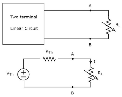
The amount of power dissipated across the load resistor is
$$P_L = I^2 R_L$$
Substitute $I = \frac{V_{Th}}{R_{Th} + R_L}$ in the above equation.
$$P_L = \lgroup \frac{V_{Th}}{(R_{Th} + R_L)} \rgroup ^2 R_L$$
$\Rightarrow P_L = {V_{Th}}^2 \lbrace \frac{R_L}{(R_{Th} + R_L)^2} \rbrace$ Equation 1
Condition for Maximum Power Transfer
For maximum or minimum, first derivative will be zero. So, differentiate Equation 1 with respect to RL and make it equal to zero.
$$\frac{dP_L}{dR_L} = {V_{Th}}^2 \lbrace \frac{(R_{Th} + R_L)^2 \times 1 - R_L \times 2(R_{Th} + R_L)}{(R_{Th} + R_L)^4} \rbrace = 0$$
$$\Rightarrow (R_{Th} + R_L)^2 -2R_L(R_{Th} + R_L) = 0$$
$$\Rightarrow (R_{Th} + R_L)(R_{Th} + R_L - 2R_L) = 0$$
$$\Rightarrow (R_{Th} - R_L) = 0$$
$$\Rightarrow R_{Th} = R_L\:or\:R_L = R_{Th}$$
Therefore, the condition for maximum power dissipation across the load is $R_L = R_{Th}$. That means, if the value of load resistance is equal to the value of source resistance i.e., Thevenins resistance, then the power dissipated across the load will be of maximum value.
The value of Maximum Power Transfer
Substitute $R_L = R_{Th}\:\&\:P_L = P_{L, Max}$ in Equation 1.
$$P_{L, Max} = {V_{Th}}^2 \lbrace \frac{R_{Th}}{(R_{Th} + R_{Th})^2} \rbrace$$
$$P_{L, Max} = {V_{Th}}^2 \lbrace \frac{R_{Th}}{4 {R_{Th}}^2} \rbrace$$
$$\Rightarrow P_{L, Max} = \frac{{V_{Th}}^2}{4 R_{Th}}$$
$$\Rightarrow P_{L, Max} = \frac{{V_{Th}}^2}{4 R_{L}}, \: since \: R_{L} = R_{Th}$$
Therefore, the maximum amount of power transferred to the load is
$$P_{L, Max} = \frac{{V_{Th}}^2}{4R_{L}} = \frac{{V_{Th}}^2}{4R_{Th}}$$
Efficiency of Maximum Power Transfer
We can calculate the efficiency of maximum power transfer, $\eta_{Max}$ using following formula.
$\eta_{Max} = \frac{P_{L, Max}}{P_S}$ Equation 2
Where,
$P_{L, Max}$ is the maximum amount of power transferred to the load.
$P_S$ is the amount of power generated by the source.
The amount of power generated by the source is
$$P_S = I^2 R_{Th} + I^2 R_L$$
$$\Rightarrow P_S = 2 I^2 R_{Th},\:since\:R_{L} = R_{Th}$$
Substitute $I = \frac{V_{Th}}{2 R_{Th}}$ in the above equation.
$$P_S = 2\lgroup \frac{V_{Th}}{2 R_{Th}} \rgroup ^2 R_{Th}$$
$$\Rightarrow P_S = 2\lgroup \frac{{V_{Th}}^2}{4 {R_{Th}}^2} \rgroup R_{Th}$$
$$\Rightarrow P_S = \frac{{V_{Th}}^2}{2 R_{Th}}$$
Substitute the values of $P_{L, Max}$ and $P_S$ in Equation 2.
$$\eta_{Max} = \frac{\lgroup \frac{{V_{Th}}^2}{4R_{Th}} \rgroup}{\lgroup \frac{{V_{Th}}^2}{2R_{Th}}\rgroup}$$
$$\Rightarrow \eta_{Max} = \frac{1}{2}$$
We can represent the efficiency of maximum power transfer in terms of percentage as follows −
$$\% \eta_{Max} = \eta_{Max} \times 100\%$$
$$\Rightarrow \% \eta_{Max} = \lgroup \frac{1}{2} \rgroup \times 100\%$$
$$\Rightarrow \% \eta_{Max} = 50\%$$
Therefore, the efficiency of maximum power transfer is 50 %.
Example
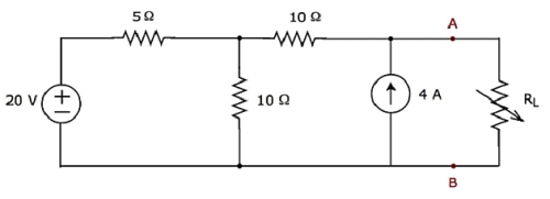
Find the maximum power that can be delivered to the load resistor RL of the circuit shown in the following figure.
Step 1 − In Thevenins Theorem chapter, we calculated the Thevenins equivalent circuit to the left side of terminals A & B. We can use this circuit now. It is shown in the following figure.
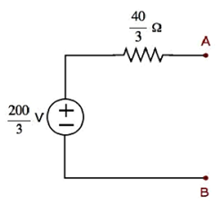
Here, Thevenins voltage $V_{Th} = \frac{200}{3}V$ and Thevenins resistance $R_{Th} = \frac{40}{3} \Omega$
Step 2 − Replace the part of the circuit, which is left side of terminals A & B of the given circuit with the above Thevenins equivalent circuit. The resultant circuit diagram is shown in the following figure.
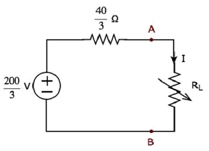
Step 3 − We can find the maximum power that will be delivered to the load resistor, RL by using the following formula.
$$P_{L, Max} = \frac{{V_{Th}}^2}{4 R_{Th}}$$
Substitute $V_{Th} = \frac{200}{3}V$ and $R_{Th} = \frac{40}{3} \Omega$ in the above formula.
$$P_{L, Max} = \frac{\lgroup \frac{200}{3} \rgroup ^ 2}{4 \lgroup \frac{40}{3}\rgroup } $$
$$P_{L, Max} = \frac{250}{3} W$$
Therefore, the maximum power that will be delivered to the load resistor RL of the given circuit is $\mathbf {\frac{250}{3}}$ W
