- Network Theory - Home
- Network Theory - Overview
- Example Problems
- Network Theory - Active Elements
- Network Theory - Passive Elements
- Network Theory - Kirchhoff’s Laws
- Electrical Quantity Division Principles
- Network Theory - Nodal Analysis
- Network Theory - Mesh Analysis
- Network Theory - Equivalent Circuits
- Equivalent Circuits Example Problem
- Delta to Star Conversion
- Star to Delta Conversion
- Network Theory - Network Topology
- Network Topology Matrices
- Superposition Theorem
- Thevenin’s Theorem
- Network Theory - Norton’s Theorem
- Maximum Power Transfer Theorem
- Response of DC Circuits
- Response of AC Circuits
- Network Theory - Series Resonance
- Parallel Resonance
- Network Theory - Coupled Circuits
- Two-Port Networks
- Two-Port Parameter Conversions
- Network Theory - Filters
Network Theory - Superposition Theorem
Superposition theorem is based on the concept of linearity between the response and excitation of an electrical circuit. It states that the response in a particular branch of a linear circuit when multiple independent sources are acting at the same time is equivalent to the sum of the responses due to each independent source acting at a time.
In this method, we will consider only one independent source at a time. So, we have to eliminate the remaining independent sources from the circuit. We can eliminate the voltage sources by shorting their two terminals and similarly, the current sources by opening their two terminals.
Therefore, we need to find the response in a particular branch n times if there are n independent sources. The response in a particular branch could be either current flowing through that branch or voltage across that branch.
Procedure of Superposition Theorem
Follow these steps in order to find the response in a particular branch using superposition theorem.
Step 1 − Find the response in a particular branch by considering one independent source and eliminating the remaining independent sources present in the network.
Step 2 − Repeat Step 1 for all independent sources present in the network.
Step 3 − Add all the responses in order to get the overall response in a particular branch when all independent sources are present in the network.
Example
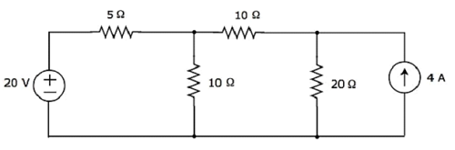
Find the current flowing through 20 Ω resistor of the following circuit using superposition theorem.
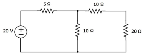
Step 1 − Let us find the current flowing through 20 Ω resistor by considering only 20 V voltage source. In this case, we can eliminate the 4 A current source by making open circuit of it. The modified circuit diagram is shown in the following figure.
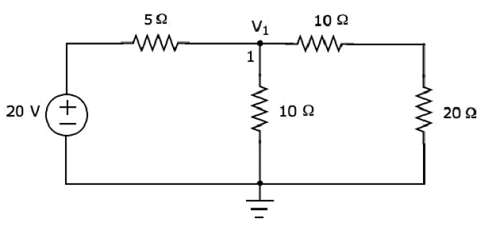
There is only one principal node except Ground in the above circuit. So, we can use nodal analysis method. The node voltage V1 is labelled in the following figure. Here, V1 is the voltage from node 1 with respect to ground.
The nodal equation at node 1 is
$$\frac{V_1 - 20}{5} + \frac{V_1}{10} + \frac{V_1}{10 + 20} = 0$$
$$\Rightarrow \frac{6V_1 - 120 + 3V_1 + V_1}{30} = 0$$
$$\Rightarrow 10V_1 = 120$$
$$\Rightarrow V_1 = 12V$$
The current flowing through 20 Ω resistor can be found by doing the following simplification.
$$I_1 = \frac{V_1}{10 + 20}$$
Substitute the value of V1 in the above equation.
$$I_1 = \frac{12}{10 + 20} = \frac{12}{30} = 0.4 A$$
Therefore, the current flowing through 20 Ω resistor is 0.4 A, when only 20 V voltage source is considered.
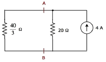
Step 2 − Let us find the current flowing through 20 Ω resistor by considering only 4 A current source. In this case, we can eliminate the 20 V voltage source by making short-circuit of it. The modified circuit diagram is shown in the following figure.
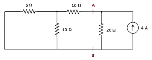
In the above circuit, there are three resistors to the left of terminals A & B. We can replace these resistors with a single equivalent resistor. Here, 5 Ω & 10 Ω resistors are connected in parallel and the entire combination is in series with 10 Ω resistor.
The equivalent resistance to the left of terminals A & B will be
$$R_{AB} = \lgroup \frac{5 \times 10}{5 + 10} \rgroup + 10 = \frac{10}{3} + 10 = \frac{40}{3} \Omega$$
The simplified circuit diagram is shown in the following figure.
We can find the current flowing through 20 Ω resistor, by using current division principle.
$$I_2 = I_S \lgroup \frac{R_1}{R_1 + R_2} \rgroup$$
Substitute $I_S = 4A,\: R_1 = \frac{40}{3} \Omega$ and $R_2 = 20 \Omega$ in the above equation.
$$I_2 = 4 \lgroup \frac{\frac{40}{3}}{\frac{40}{3} + 20} \rgroup = 4 \lgroup \frac{40}{100} \rgroup = 1.6 A$$
Therefore, the current flowing through 20 Ω resistor is 1.6 A, when only 4 A current source is considered.
Step 3 − We will get the current flowing through 20 Ω resistor of the given circuit by doing the addition of two currents that we got in step 1 and step 2. Mathematically, it can be written as
$$I = I_1 + I_2$$
Substitute, the values of I1 and I2 in the above equation.
$$I = 0.4 + 1.6 = 2 A$$
Therefore, the current flowing through 20 resistor of given circuit is 2 A.
Note − We cant apply superposition theorem directly in order to find the amount of power delivered to any resistor that is present in a linear circuit, just by doing the addition of powers delivered to that resistor due to each independent source. Rather, we can calculate either total current flowing through or voltage across that resistor by using superposition theorem and from that, we can calculate the amount of power delivered to that resistor using $I^2 R$ or $\frac{V^2}{R}$.
