- Network Theory - Home
- Network Theory - Overview
- Example Problems
- Network Theory - Active Elements
- Network Theory - Passive Elements
- Network Theory - Kirchhoff’s Laws
- Electrical Quantity Division Principles
- Network Theory - Nodal Analysis
- Network Theory - Mesh Analysis
- Network Theory - Equivalent Circuits
- Equivalent Circuits Example Problem
- Delta to Star Conversion
- Star to Delta Conversion
- Network Theory - Network Topology
- Network Topology Matrices
- Superposition Theorem
- Thevenin’s Theorem
- Network Theory - Norton’s Theorem
- Maximum Power Transfer Theorem
- Response of DC Circuits
- Response of AC Circuits
- Network Theory - Series Resonance
- Parallel Resonance
- Network Theory - Coupled Circuits
- Two-Port Networks
- Two-Port Parameter Conversions
- Network Theory - Filters
Equivalent Circuits Example Problem
In the previous chapter, we discussed about the equivalent circuits of series combination and parallel combination individually. In this chapter, let us solve an example problem by considering both series and parallel combinations of similar passive elements.
Example
Let us find the equivalent resistance across the terminals A & B of the following electrical network.
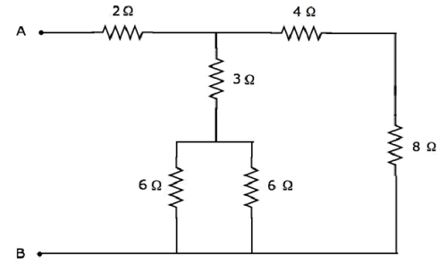
We will get the equivalent resistance across terminals A & B by minimizing the above network into a single resistor between those two terminals. For this, we have to identify the combination of resistors that are connected in series form and parallel form and then find the equivalent resistance of the respective form in every step.
The given electrical network is modified into the following form as shown in the following figure.
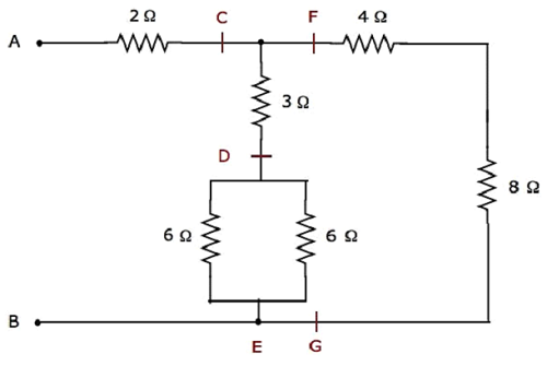
In the above figure, the letters, C to G, are used for labelling various terminals.
Step 1 − In the above network, two 6 Ω resistors are connected in parallel. So, the equivalent resistance between D & E will be 3 Ω. This can be obtained by doing the following simplification.
$$R_{DE} = \frac{6 \times 6}{6 + 6} = \frac{36}{12} = 3 \Omega$$
In the above network, the resistors 4 Ω and 8 Ω are connected in series. So, the equivalent resistance between F & G will be 12 Ω. This can be obtained by doing the following simplification.
$$R_{FG} = 4 + 8 = 12 \Omega$$
Step 2 − The simplified electrical network after Step 1 is shown in the following figure.
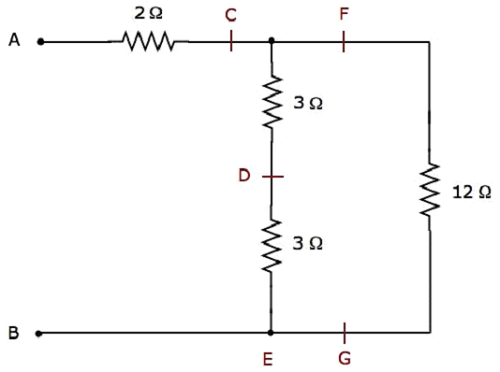
In the above network, two 3 Ω resistors are connected in series. So, the equivalent resistance between C & E will be 6 Ω. This can be obtained by doing the following simplification.
$$R_{CE} = 3 + 3 = 6 \Omega$$
Step 3 − The simplified electrical network after Step 2 is shown in the following figure.
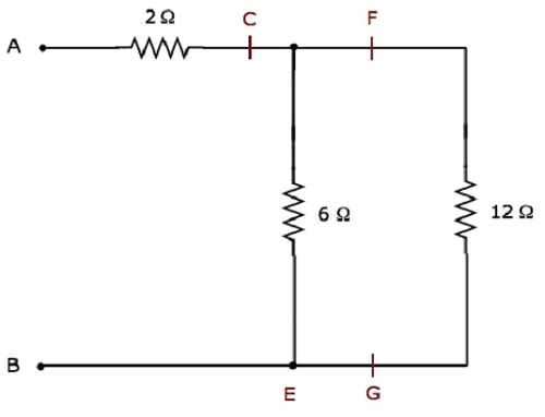
In the above network, the resistors 6 Ω and 12 Ω are connected in parallel. So, the equivalent resistance between C & B will be 4 Ω. This can be obtained by doing the following simplification.
$$R_{CB} = \frac{6 \times 12}{6 + 12} = \frac{72}{18} = 4 \Omega$$
Step 4 − The simplified electrical network after Step 3 is shown in the following figure.
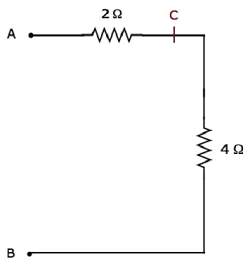
In the above network, the resistors 2 Ω and 4 Ω are connected in series between the terminals A & B. So, the equivalent resistance between A & B will be 6 Ω. This can be obtained by doing the following simplification.
$$R_{AB} = 2 + 4 = 6 \Omega$$
Therefore, the equivalent resistance between terminals A & B of the given electrical network is 6 Ω.
