- Network Theory - Home
- Network Theory - Overview
- Example Problems
- Network Theory - Active Elements
- Network Theory - Passive Elements
- Network Theory - Kirchhoff’s Laws
- Electrical Quantity Division Principles
- Network Theory - Nodal Analysis
- Network Theory - Mesh Analysis
- Network Theory - Equivalent Circuits
- Equivalent Circuits Example Problem
- Delta to Star Conversion
- Star to Delta Conversion
- Network Theory - Network Topology
- Network Topology Matrices
- Superposition Theorem
- Thevenin’s Theorem
- Network Theory - Norton’s Theorem
- Maximum Power Transfer Theorem
- Response of DC Circuits
- Response of AC Circuits
- Network Theory - Series Resonance
- Parallel Resonance
- Network Theory - Coupled Circuits
- Two-Port Networks
- Two-Port Parameter Conversions
- Network Theory - Filters
Network Theory - Network Topology
Network topology is a graphical representation of electric circuits. It is useful for analyzing complex electric circuits by converting them into network graphs. Network topology is also called as Graph theory.
Basic Terminology of Network Topology
Now, let us discuss about the basic terminology involved in this network topology.
Graph
Network graph is simply called as graph. It consists of a set of nodes connected by branches. In graphs, a node is a common point of two or more branches. Sometimes, only a single branch may connect to the node. A branch is a line segment that connects two nodes.
Any electric circuit or network can be converted into its equivalent graph by replacing the passive elements and voltage sources with short circuits and the current sources with open circuits. That means, the line segments in the graph represent the branches corresponding to either passive elements or voltage sources of electric circuit.
Example
Let us consider the following electric circuit.
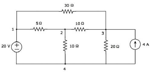
In the above circuit, there are four principal nodes and those are labelled with 1, 2, 3, and 4. There are seven branches in the above circuit, among which one branch contains a 20 V voltage source, another branch contains a 4 A current source and the remaining five branches contain resistors having resistances of 30 Ω, 5 Ω, 10 Ω, 10 Ω and 20 Ω respectively.
An equivalent graph corresponding to the above electric circuit is shown in the following figure.
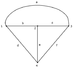
In the above graph, there are four nodes and those are labelled with 1, 2, 3 & 4 respectively. These are same as that of principal nodes in the electric circuit. There are six branches in the above graph and those are labelled with a, b, c, d, e & f respectively.
In this case, we got one branch less in the graph because the 4 A current source is made as open circuit, while converting the electric circuit into its equivalent graph.
From this Example, we can conclude the following points −
The number of nodes present in a graph will be equal to the number of principal nodes present in an electric circuit.
The number of branches present in a graph will be less than or equal to the number of branches present in an electric circuit.
Types of Graphs
Following are the types of graphs −
- Connected Graph
- Unconnected Graph
- Directed Graph
- Undirected Graph
Now, let us discuss these graphs one by one.
Connected Graph
If there exists at least one branch between any of the two nodes of a graph, then it is called as a connected graph. That means, each node in the connected graph will be having one or more branches that are connected to it. So, no node will present as isolated or separated.
The graph shown in the previous Example is a connected graph. Here, all the nodes are connected by three branches.
Unconnected Graph
If there exists at least one node in the graph that remains unconnected by even single branch, then it is called as an unconnected graph. So, there will be one or more isolated nodes in an unconnected graph.
Consider the graph shown in the following figure.
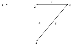
In this graph, the nodes 2, 3, and 4 are connected by two branches each. But, not even a single branch has been connected to the node 1. So, the node 1 becomes an isolated node. Hence, the above graph is an unconnected graph.
Directed Graph
If all the branches of a graph are represented with arrows, then that graph is called as a directed graph. These arrows indicate the direction of current flow in each branch. Hence, this graph is also called as oriented graph.
Consider the graph shown in the following figure.
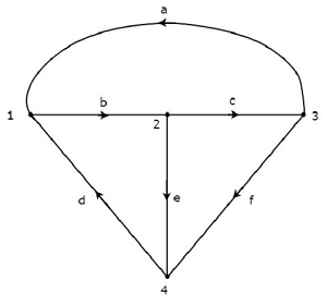
In the above graph, the direction of current flow is represented with an arrow in each branch. Hence, it is a directed graph.
Undirected Graph
If the branches of a graph are not represented with arrows, then that graph is called as an undirected graph. Since, there are no directions of current flow, this graph is also called as an unoriented graph.
The graph that was shown in the first Example of this chapter is an unoriented graph, because there are no arrows on the branches of that graph.
Subgraph and its Types
A part of the graph is called as a subgraph. We get subgraphs by removing some nodes and/or branches of a given graph. So, the number of branches and/or nodes of a subgraph will be less than that of the original graph. Hence, we can conclude that a subgraph is a subset of a graph.
Following are the two types of subgraphs.
- Tree
- Co-Tree
Tree
Tree is a connected subgraph of a given graph, which contains all the nodes of a graph. But, there should not be any loop in that subgraph. The branches of a tree are called as twigs.
Consider the following connected subgraph of the graph, which is shown in the Example of the beginning of this chapter.
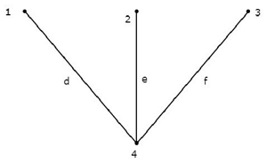
This connected subgraph contains all the four nodes of the given graph and there is no loop. Hence, it is a Tree.
This Tree has only three branches out of six branches of given graph. Because, if we consider even single branch of the remaining branches of the graph, then there will be a loop in the above connected subgraph. Then, the resultant connected subgraph will not be a Tree.
From the above Tree, we can conclude that the number of branches that are present in a Tree should be equal to n - 1 where n is the number of nodes of the given graph.
Co-Tree
Co-Tree is a subgraph, which is formed with the branches that are removed while forming a Tree. Hence, it is called as Complement of a Tree. For every Tree, there will be a corresponding Co-Tree and its branches are called as links or chords. In general, the links are represented with dotted lines.
The Co-Tree corresponding to the above Tree is shown in the following figure.
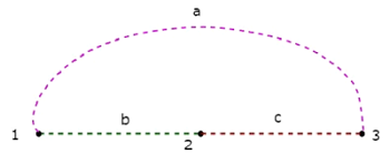
This Co-Tree has only three nodes instead of four nodes of the given graph, because Node 4 is isolated from the above Co-Tree. Therefore, the Co-Tree need not be a connected subgraph. This Co-Tree has three branches and they form a loop.
The number of branches that are present in a co-tree will be equal to the difference between the number of branches of a given graph and the number of twigs. Mathematically, it can be written as
$$l = b - (n - 1)$$
$$l = b - n + 1$$
Where,
- l is the number of links.
- b is the number of branches present in a given graph.
- n is the number of nodes present in a given graph.
If we combine a Tree and its corresponding Co-Tree, then we will get the original graph as shown below.
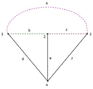
The Tree branches d, e & f are represented with solid lines. The Co-Tree branches a, b & c are represented with dashed lines.
